Diminishing numbers of skilled tradesmen in the workforce and the need to reduce production costs have caused machine tool automation to proliferate during the past decade. At one time, only the largest manufacturers took advantage of machine tool options such as part probing, tool setting and conversational programming. Often, these options were only available on more expensive machine tools and out of reach for most small shops. Now, even the smallest, lowest-cost, commodity machine offers probing and tool setting.
Parametric programming is the vehicle that drives these automated processes. Parametric programming stores data in external tables or files, rather than within the part program itself, and the program accesses the data when needed. This enables users to change data values with relative ease.
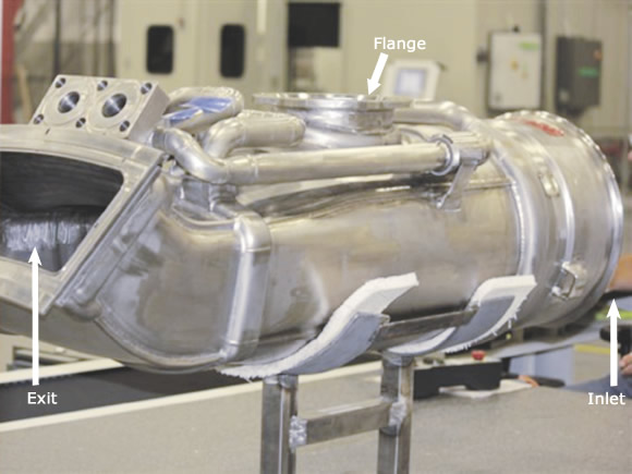
Figure 1. The flange and inlet are probed, and the coordinates are used to calculate the position of the oblique exit face.
In addition, parametric programming is typically the foundation on which a macro program is based. Macro programs drive part probing, tool setting and many canned cycles found on a conversational CNC. Macros allow the user to invoke numerous program commands with only a few characters.
Macro programming and parametric programming are independent concepts. However, the machine tool world has adapted “macro” to describe all of the functions associated with parametric and macro programming. Therefore, I will use macro in the same context throughout this article.
Macros are a powerful tool and available on almost every machine tool control. Macro programming allows a programmer to be creative, and creativity can help drive efficiency.
CNC code consists of basic commands that control the direction of tool motion, cutting speeds and machine tool functions. Macro programming lets the machine “think” by allowing the programming to perform arithmetic operations, use logic statements, access the control memory and poll the machine tool for positional information.
The following is an example of CNC code that demonstrates the arithmetic capabilities of a program.
#551=[COS[52]*#550]+441
#552=COS[38]*[ABS[#7621]]
#553=#551-#552
#554=-1*[1800-[ABS[#553]]]
#555=-1*[1800-[#550+[ABS [#7624]]]]
#556=-1*[1800-[[ABS [#7621]]+563]]
It is a portion of a program that I developed for setting the coordinate systems for one of our more complex parts, a large weldment machined in three different planes (Figure 1). Tolerances, part size and desired cycle times dictate we machine it in one setup. Because the part is a weldment and all of the components are formed, there are no reliable surfaces to use for positioning the part in a fixture.
To overcome this problem, I used the canned probing routines to find the large flange in the center and the center of the inlet. The coordinate system for the face that is oblique to the body must be calculated using trigonometry. I used the coordinate systems from the other faces, which were found using the probe, to calculate the position of the oblique face. These coordinates were then saved to the control and recalled when needed.
My method for setting the part eliminated the need to make qualifying cuts in a separate setup and reduced the chance of creating bad parts because the part is machined in one setup.
Macro programming also offers the ability to use logic expressions. Logic makes it possible to let the control make decisions for the operator.
Mostly, our shop machines welded assemblies. Machining stock allowances are small because the parts are designed to minimize consumption of expensive nickel-base superalloys. Therefore, part placement during assembly is critical because any deviation from the designed location can create a situation where there is not enough material to machine.
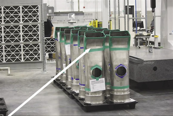
The indicated profile, which can vary by several millimeters, is trimmed using the macro that creates a custom toolpath.
To ensure there’s enough material, we probe the part and set the work offsets. Once we have calculated the desired finish plane for a surface, we probe the stock surface and compare the position of the actual surface to the desired position. The difference in these values represents the amount of stock on the part.
We can then ask the control to compare the desired stock value to the actual and use an “if” statement to send an error message to the operator, telling him not to begin work. Having the logic expressions allows the programmer to force the control to make decisions based on date or machine condition and, ultimately, have a program with multiple outcomes.
The most powerful feature available in macro programming is the ability to poll the machine control for positional information. It is possible to tell the control to remember the current machine position and then recall it later to perform calculations, develop logic statements or, in our case, create toolpaths.
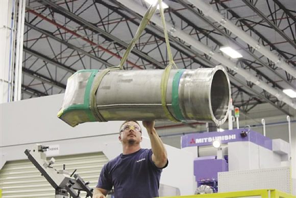
Machinist/welder Jason LaBarge loads a weldment into the machining fixture.
On the part’s exit end, we machine a complex profile around the periphery. Deformation from welding causes the exit profile to vary from part to part. Previously, we used a die grinder and abrasive cut off wheel to manually make the necessary cuts because of inconsistencies from upstream processing. The manual cutting could take up to 8 hours per part.
To overcome this issue we developed a routine to probe the part periphery more than 200 times and store each coordinate. Once probing is completed, we call up the macro program, which uses the stored values to create a toolpath for the part periphery. Now, each part has a unique toolpath, and we have reduced the time to perform the operation by 6 hours.
Macro and parametric programming techniques are not difficult to use or learn. They can be very powerful tools that provide access to new problem-solving methods. CTE
About the Author: Christopher Tate is manufacturing engineering lead for machining at Mitsubishi Power Systems, Savannah (Ga.) Machinery Works, a global builder of gas and steam turbines. He has 20 years of experience in the metalworking industry and holds a Master of Science and Bachelor of Science from Mississippi State University. E-mail: [email protected].Related Glossary Terms
- abrasive
abrasive
Substance used for grinding, honing, lapping, superfinishing and polishing. Examples include garnet, emery, corundum, silicon carbide, cubic boron nitride and diamond in various grit sizes.
- computer numerical control ( CNC)
computer numerical control ( CNC)
Microprocessor-based controller dedicated to a machine tool that permits the creation or modification of parts. Programmed numerical control activates the machine’s servos and spindle drives and controls the various machining operations. See DNC, direct numerical control; NC, numerical control.
- conversational programming
conversational programming
Method for using plain English to produce G-code file without knowing G-code in order to program CNC machines.
- fixture
fixture
Device, often made in-house, that holds a specific workpiece. See jig; modular fixturing.
- metalworking
metalworking
Any manufacturing process in which metal is processed or machined such that the workpiece is given a new shape. Broadly defined, the term includes processes such as design and layout, heat-treating, material handling and inspection.
- superalloys
superalloys
Tough, difficult-to-machine alloys; includes Hastelloy, Inconel and Monel. Many are nickel-base metals.
- toolpath( cutter path)
toolpath( cutter path)
2-D or 3-D path generated by program code or a CAM system and followed by tool when machining a part.
Author

Christopher Tate is the owner of Tate Engineering, a Natchez, Mississippi, firm that helps manufacturers solve efficiency problems. Tate, who earned master's degree in industrial technology from Mississippi State University, has 32 years of experience in the metalworking industry.