Pipe Tapping
Pipe Tapping
Taper pipe threading is unlike any other threading operation, and it may be one of the most difficult operations a machinist can be asked to perform. This article reviews the various types of taper threads and the tools and techniques needed to produce them.
Taper pipe threads are not like standard machine threads in the way they are used or in the way they are made.
One of the more challenging operations in metalcutting is taper pipe thread tapping. Those familiar with the process consider it to be more difficult than machine thread tapping. Taper pipe thread tapping requires greater accuracy, and it subjects the tools to higher stresses. Pipe threads must be formed more accurately, because 100% of the thread height must be cut by the tap or other pipe-threading tool to maintain the standard thread profile.
Machinists must use special techniques to produce taper pipe threads, because the threads must serve an entirely different purpose than machine threads or nuts and bolts. Pipe threads are designed and cut so that they can mechanically seal a threaded joint for pressure and prevent leakage. The tapered thread permits pipes to be disassembled and reassembled frequently. And it lets users assemble pipes with a new thread to an old thread by just wrenching up tighter and relying on the taper to increase fit tightness.
Pipe Thread Varieties
The taper pipe thread has been serving its purpose well for many years. When the Briggs Standard taper pipe thread was developed 160 years ago, it made a substantial contribution to the improvement of the steam engine. The basic dimensions for the thread remain unchanged in today's standards. The rate of taper was and still is 3/4" per foot (or 0.0625" per inch).
There are other pipe threads designed for gas and hydraulic applications, hose couplings, mechanical joints, and other purposes. These threads were developed at later dates and their features differ from standard taper pipe threads. Table 1 lists the various pipe threads, their designation symbols, and uses. Some are straight threads and some are tapered. Generally, the following recommendations for producing NPT-type taper pipe threads apply to the other types of tapered threads as well.
The regular NPT system, in which both threaded parts have a taper thread, is generally used in normal pressure fittings. Usually, some kind of chemical sealer or tape is used to ensure a tight fit.
The NPTF, or dryseal, system is similar to NPT, but the machinist must adhere to tighter tolerances when cutting NPTF threads. An accurately cut thread profile is necessary to ensure that when the connection between the threaded parts is tightened the thread crest and root contact before the thread flanks do so that contact is established along the entire thread profile when the parts are assembled.
Full contact allows the threads to serve as a mechanical seal and eliminates the need for sealing material between the threads. Metal-to-metal contact is desirable whenever contact between a sealing compound and the fluid being carried in the pipe might cause problems. The performance of substances such as some petroleum-base products and hydraulic fluids can be compromised when contaminated by a sealing compound. Conversely, the performance of the sealing compound may be compromised by contact with the fluid carried in the pipe.
There are other threading systems in addition to NPT and NPTF. ANPT, for instance, is basically an improved version of NPT for aerospace applications that require a higher level of gaging. The NPSI system, commonly used in automotive brake systems and heater-hose connections, features a straight dryseal thread as the internal thread mated to a tapered dryseal external thread.
Taper Tapping Techniques
Machinists who are familiar with standard tapping will require some re-education to produce taper pipe threads. Even the designations for taper pipe thread taps are different. A machinist looking at a 1/2-14 pipe tap is likely to note that the tap diameter is larger than 1/2". In fact, the tap's diameter at the large end is 0.865". The tap's designation refers to the inner diameter (ID) of the standard iron pipe it is designed to thread. Therefore, a 1/2-14 taper pipe thread tap is designed to tap a 1/2" ID pipe. Keep in mind, the external thread on a pipe with a 1/2" ID is at least the size of the ID plus the amount of two wall thicknesses. An internally threaded coupling, or elbow, must be of comparable size to assemble the threaded pipe.
Another difference between taper pipe thread tapping and machine thread tapping is in the way the machinist controls the thread diameter. Using a taper pipe thread tap, the machinist can reduce or increase the thread diameter by adjusting the depth that the tap cuts into the hole. To achieve the basic thread depth, a machinist typically drives the tap into the workpiece 12 turns. More turns will drive the tap deeper into the workpiece and produce a larger diameter thread. Fewer turns will produce a smaller diameter thread. There are no H-limits for the taper pipe tap sizes, and there is no particular thread-product class of fit, such as 2A/2B. The application, with proper gaging, will determine the appropriate depth for the proper mating of the parts.
Gaging Taps and Threads
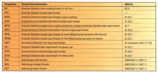
Table 1: The various types of pipe threads and their uses. (Click for larger image)Evaluating, or gaging, taper pipe tap threads and actual pipe thread size is accomplished by the use of taper thread gages (Figure 1). The L-1 ring gage is used to check the external pipe thread size and is also used to measure the pipe tap size.
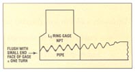
Figure 1: An L-1 ring gage is used to evaluate an NPT tap's threads. (Click for larger image)Machinists gage taps by measuring their "projection." The term refers to the amount the tap projects through the L-1 ring gage, or the distance from the extreme thread end of the tap to the front side of the gage (Figure 2). If a machinist knows this distance, he will also know the tap's diameter, including its major, pitch, and minor diameters. Each taper pipe tap size has a corresponding "standard projection" value, as set by the industry.
When gaging a taper pipe tap, the tap's diameter is measured at the gage line. This point is where the backside of the L-1 ring gage touches the tap. Therefore, the critical measurement that will determine the tap's diameter is actually from the backside of the gage to the extreme thread end. This measurement is called the run, and it is rather difficult to measure. Machinists simplify this measurement by subtracting the thickness of the ring gage from the specified run and using this value to determine the proper projection from the front side of the gage.
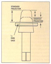
Figure 2: A pipe tap's projection is the amount it extends beyond the front of a ring gage. For special applications this projection may be shortened while the rest of the tap's geometry remains the same. (Click for larger image)In some applications the machinist may encounter a hole with a restriction at the bottom that does not allow a standard taper pipe tap to be driven to the depth needed to achieve the specified thread diameter. In these cases the machinist will have to use a tap with a nonstandard projection that will produce the correct size pipe thread in fewer than 12 turns. This is commonly referred to as a "short projection" pipe tap. It is basically a standard pipe tap manufactured with a projection shorter than the industry standard value (Figure 2). These taps can be ordered as specials.
Machinists use one or more tapered thread plug gages to evaluate tapped taper pipe holes. An L-1 plug gage would be used to evaluate an NPT threaded hole, for example. When a plug gage is inserted into a properly threaded hole, a step, or notch, on the gage will line up with the surface of the workpiece, plus or minus one thread. If the thread size of the first hole is wrong, the machinist can correct the problem on subsequent holes by increase the tapping depth to enlarge the thread size or decreasing the depth to reduce the size.
Machinists have adopted a quick way to monitor the depth of their tapping. They wind a piece of wire or tape around the tap at the gage line to serve as a depth indicator. This common practice is a neat trick, but it severely restricts chip ejection and the flow of coolant into the hole. Because this practice can lead to torn threads and premature tap failure, it should not be done. A safer alternative is to use a thread gage frequently to ensure the correct tapping depth and thread size.
Machinists who are used to tapping threads with a 60% to 75% thread height will find that cutting threads with a 100% thread height presents a unique challenge. Actually, the taper pipe tap has to cut more than 100% of the thread to ensure a fully profiled thread when done. The taper makes the tapping operation even more difficult, because it causes the tap to be extremely tight in the hole when the tap has been driven to the required depth. The tap becomes wedged at this point, and considerable force is required to break it loose to reverse it.
Once the tap is broken loose, it becomes entirely loose in about 1/8 of a turn. This play presents a hazard when the tap is reversed out of the hole. With only a little overfeeding or underfeeding, the tap can wipe out the threads as it is backed out. For this reason, lead control is highly critical in taper pipe thread tapping.
Reaming Risks
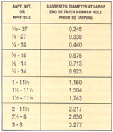
Table 2: The correct diameter at the wider end of a taper reamed hole for various size taps. (Click for larger image)One practice that is frequently recommended for taper pipe tapping may not be necessary. Many in the industry believe that holes should be reamed with a taper pipe reamer before tapping. However, this reaming operation can cause the tap to cut unacceptable threads, and it shortens the tap life if the reaming depth is not closely controlled. Table 2 shows what the diameter should be at the large end of the taper reamed hole prior to tapping. A hole reamed to this size is equal to the minor diameter of the threads when the hole is tapped. Reaming an oversize hole will result in insufficient thread height. If the reamed hole is too small, it will subject the tap to an extreme metal-cutting load.
Even a correctly reamed hole will subject the tap to some extreme forces at the cutting points, or thread crests, because all the teeth start cutting at once. Starting at these points, the metal-cutting action is inward toward the tap's cross-sectional center. When a tap cuts threads in a straight-walled, nonreamed hole, the force progresses through the chamfered threads and then through one thread at a time as the tap rotates forward.
Unless there are compelling reasons for taper pipe reaming, it is best to adjust the drilled holes so that they can be tapped without reaming. In some cases-such as in a high-pressure assembly where four or more fully profiled, or "perfect," threads are required- reaming will be called for. But in most cases, tapping a nonreamed hole will produce enough "perfect" threads to satisfy thread sealing and holding requirements. In other words, taper pipe reaming should not be considered standard operating procedure.
Styles and Hooks
When ordering pipe taps, it is particularly important to consider and specify the type of material being tapped. The tap's style will have a significant impact on thread quality and tap performance. Styles such as full-thread, interrupted-thread, and spiral-flute are available for specific applications.
Interrupted-thread pipe taps are recommended for tapping hard or tough materials. If premature chipping and breakage is a problem, an interrupted thread pipe tap may perform better, because surface contact is reduced to help relieve tapping torque and improve lubrication. The interrupted-thread tap may not last as long because it has fewer cutting points, but where taps are failing due to chipping rather than wear, wear resistance is not of primary importance. Also, the reduced surface contact of an interrupted-thread style might help prevent torn threads. Threads can tear when the tap becomes stuck in the hole once it stops rotating at the end of its forward motion. When the tap is reversed, the material stuck to it is ripped away. By resisting the material's tendency to stick to the tap threads, an interrupted thread can be reversed without damaging the threads. Interrupted threads are available in standard NPT and NPTF thread forms. The style can be ordered in a variety of other pipe tap styles as well.
A tap's hook, surface treatment, and coating also will influence its performance. Taps are available with low (0°-3°), medium (8°-12°), or high (15°-18°) hooks. There are a wide variety of surface treatments and coatings available today to help extend tap life, improve thread finish, and reduce tapping torque.
As an alternative to tapping pipe threads, a shop might produce the thread by roll forming. However, a shop should consider both the advantages and disadvantages of roll forming before making such a choice. Not all manufacturers supply this type of threadmaking tool. In use, thread-rolling tools must be kept under tighter control than pipe thread taps. In thread rolling, the hole size is very critical to the production of a 100% thread height. The holder used for thread rolling should have a torque-limit feature. Caution should be used when thread rolling die-cast aluminum applications, as the material becomes brittle when cold formed and may fracture. If a shop is considering thread rolling, shop engineers should consult a tap application specialist first.
It's true that taper pipe thread tapping is a difficult operation full of risks and difficulties not found in other types of tapping. But that doesn't mean it's impossible to produce good quality threads. In general, all a machinist needs to tap tapered threads successfully is a basic understanding of the product requirements, the proper tap, and the correct gaging process.
About the Author
Wes Emerson is a technical specialist with Vermont Tap & Die, Lyndonville, VT.

