New Twists on Threading: General Industry Coverage
The advent of CNCs made new threadmaking technologies practical.
Many shops have discovered that machines with rigid-tapping and thread-milling capabilities not only offer high accuracy and versatility, but also reduce the cost of threading operations. Not all shops take advantage of these machine capabilities, however. Many operators prefer floating toolholders, taps, and dies, because these tools are familiar to them. Being less acquainted with rigid tapping and thread milling, the operators may not recognize the advantages of these thread-making methods. Once the machine operators familiarize themselves with the machine requirements for these operations, a shop can begin reaping the benefits.
Rigid Tapping
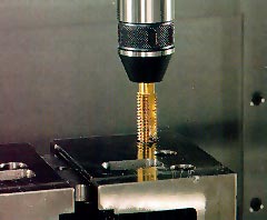
Figure 1: Rigid tapping on a machining center can produce threads with a high degree of accuracy and repeatability, while keeping tap wear to a minimum.
Available as an option on many machining centers, rigid tapping eliminates the need for special tapholders, since the taps can be held in drill collet holders (Figure 1). Rigid tapping employs an encoder mounted on a spindle shaft to measure the movement of the spindle along the z-axis and provide tool-position data to the controller. In conjunction with a canned tapping cycle, the encoder synchronizes the z-axis feed rate with spindle rotation to produce threads accurately. Side forces are eliminated on the flanks of the threads, improving accuracy and repeatability and minimizing tool wear. Rigid tapping with a machining center produces threads as well as a leadscrew tapper does, but without the expense of using a dedicated machine for the job.
If something does go wrong with a rigid-tapping operation, a hole can be retapped without cross-threading, as long as the tap and z-axis depth haven’t changed. Cross-threading, or the production of two sets of threads over the same area, occurs when the same hole is tapped twice and the lead of the thread doesn’t start in exactly the same place.
Rigid tapping also eliminates pullout and distortion of the first thread in the tapped hole. This occurs when a tension/compression holder or tapping head pulls on the tap as it is being retracted, subjecting the first thread to more force along its flank than it can withstand. Typically, this is not a problem on medium and coarse threads, but tension/compression tapping may expose fine-pitch threads to damage. Tension/compression tapping may also cause damage when tapping soft material or retracting the tap from a small-diameter hole.
Some words of caution: Because rigid tapping holds the tap rigidly in place, TIR should be no higher than 0.0002″. High runout could cause a small tap to break or a large tap to produce oversize threads. Broken taps are expensive to replace: A high-quality tap, which can thread about 50 holes, can cost up to $60. This high price tag is one reason a shop may choose thread milling for its threading operations. A thread-mill insert costs from $12 to $17, and each side will thread about 200 holes.
Thread Milling
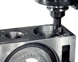
Figure 2: The same thread mill can machine threads in a wide range of hole diameters.
Thread milling is considered the most cost-effective method for threading holes greater than 1″ in diameter and holes in odd-shaped parts. The technique employs a cutter formed with the profile of the thread (Figure 2). Replaceable insert holders are typically used, because they are more economical than nonreplaceable holders. They allow precision threads to be quickly and efficiently milled in holes from 3/8″ in diameter up to almost any size within the machine’s work envelope. Thread mills can produce threads up to five times the length of the insert.
Helical interpolation, which is available even on many low-cost machining centers, allows the tool to move in a circular motion on the x- and y-axes around the hole with a simultaneous vertical axis that creates the thread pitch. A single revolution of the tool, around the ID of the hole, and a vertical move along the z-axis, the length of a single pitch, cuts a thread the same size as the length of the thread-mill insert.
Most machining centers allow helical interpolation in clockwise and counterclockwise directions, so that left- and right-hand threads can be machined with the same cutter. With a left-hand thread, the thread-milling operation starts at the top of the hole; with a right-hand thread, it starts at the bottom. This is done so that the mill can climb cut when producing either thread. Internal and external threads can be cut, but each may require a different insert.
A thread-mill insert produces a finished thread form along its full length. Inserts can accommodate threads with fine or coarse pitches, such as trapeze, Acme, and stub-Acme profiles. Typically, taps don’t machine these coarse threads as well as thread-mill inserts do. Different inserts are needed to cut different thread pitches, but the same inserts can machine a wide range of thread diameters and hole diameters. Through-hole diameters of 2″ and 10″, for example, can be milled using the same inserts.
There is very little variance in horsepower and torque requirements when thread milling different hole sizes or thread pitches on a machining center. Tapping a 10″-dia. hole on a mill, by contrast, would require very high horsepower and torque. With thread milling, the machine’s runout is not critical to the accuracy of the operation, because the operator can reset the offset on the insert.
Threading Accuracy
In any threading operation, the accuracy of the thread form is affected by pitch, pitch diameter, flank angle of the thread, tool diameter, and tool wear. Thread-mill inserts generally last longer than taps and do not wear as quickly. When an insert does wear, the thread form generally remains intact, which allows the operator to make a simple offset adjustment to correct the diameter of the thread. On a tap, however, it is not possible to adjust the offset to compensate for tool wear. When a thread-mill insert breaks, it is not the catastrophic event it is when a tap breaks, because the thread can be started with the new insert at the same place it was originally started. This allows the hole to be rethreaded without the risk of cross-threading.
Tapping is a slow process, and accuracy of the thread form must be closely monitored. In most cases, thread milling can be accomplished with one pass of the cutter. Of course, this depends on programming the insert manufacturer’s recommended speeds and feeds to
prevent cutter deflection. Many CAM systems offer thread milling as a point-and-click feature, and some programming help systems allow the user to select canned thread-milling routines.
Figure 3: The correct way to thread mill is with 90° lead-in, one full revolution, and 90° lead-out.
These canned routines usually provide the correct lead-in/lead-out, which is important to the accuracy and quality of the threads. With tapping, the lead-in and lead-out are at a random angle. With thread milling, the lead-in is designated, and the pitch is maintained. For example, starting at the bottom of the hole, the correct lead-in/lead-out is 90° lead-in, one full revolution, 90° lead-out (Figure 3). This eliminates gouges at the start of the thread caused by the straight-in/straight-out method.
With support from CAM systems and programming help systems, thread milling can be as simple as selecting the points to be threaded, choosing the tool, and entering the pitch (or z-axis movement). Once the pitch has been established, any thread diameter can be thread milled without special tooling or secondary operations.
Each method of threading has its place: While rigid tapping is suitable for applications requiring highly accurate threads, thread milling is the more efficient and economical choice for threading blind holes and producing pipe and tapered-pipe threads.
Applications
Generally, ID pipe threading with a tap requires high torque to keep the tool moving. This is because all threads along the engaged length of the tap are cut simultaneously at one point once the tap reaches its depth. With thread milling, the need to utilize peak torque is reduced. Thus, thread-mill inserts on a low-cost machining center can pipe-thread holes larger than taps on an expensive, high-torque tapping machine can.
Blind holes are difficult to tap to the bottom, because the chamfer at the tip of a tap doesn’t allow contact with the side wall to cut the last pitch. Because a thread-mill insert doesn’t have this clearance problem, it easily cuts the thread form all the way from the bottom of a blind hole. Tapping a blind hole may require as many as three tools to get the thread to the bottom. Only one tool is required for thread milling. Because fewer chips build up with thread milling than with tapping, the tool is less likely to crash into the bottom of the blind hole or crush chips that were not evacuated into the bottom of the hole.
About the Author
Peter Zierhut is marketing manager for Haas Automation Inc., Chatsworth, CA.


MFGAxis Discussion