END USER: Holmatro Inc., (410) 768-9662, holmatro-usa.com.
CHALLENGE: Produce parts faster without investing in additional fixturing.
SOLUTION: Efficiently reprogram the parts with the company's CAM software after moving part production to a multitask lathe.
SOLUTION PROVIDER: DP Technology Corp., (800) 627-8479, www.dptechnology.com.
The hero isn’t always the guy in the cape. Symbols of the modern white knight notwithstanding, sometimes he doesn’t even wear a badge or ride on a fire engine.
In this case study, the guys in the “white hats” are with Holmatro Inc., a manufacturer of rescue equipment—including hydraulic spreaders, cutters and rams—used to extricate people pinned inside vehicles after traffic accidents.
“Getting rid of the metal when someone is trapped is the first thing rescuers do when they assess the accident scene,” said Chuck Cain, manufacturing engineer at Holmatro’s Glen Burnie, Md., facility. “Anything we can do to chop minutes off at the scene can make a real difference.”
He added that the company continually invests in R&D to find ways to make better products. “Innovation is fun for me, and it all comes down to having the right tools for the job,” Cain said.
One of those tools is CAM software. When shopping for a CAM package in the past to eliminate the programming of machine tools longhand at the control, Cain noted Holmatro examined the offerings from “everybody in the CAM business” before selecting ESPRIT CAM software from DP Technology Corp., Camarillo, Calif.
Cain explained that one of the reasons for choosing ESPRIT is it helps impart specified finishes of 0.3µm Ra to 1.6µm Ra by properly adjusting the speeds and feeds during machining based on cutting conditions. This is especially critical when producing parts with contoured surfaces. “ESPRIT keeps everything consistent,” he said.
Smooth bore surfaces are essential for hydraulic components. This is because the company’s pumps flow hydraulic fluid at 10,500 psi, and the high-pressure flow increases the effects of any imperfection by making it bigger, such as a line, on a bore for a hydraulic cylinder, Cain pointed out. “It gets real ugly quickly, because any surface imperfections create a path for hydraulic oil to flow between the cylinder wall and the O-ring,” he said. “At 10,500 psi, that path would cause the O-ring to fail.”
More recently, Cain noted the CAM software provided a solution when the vice president tasked him with boosting throughput for runs of 300 pump coupling adapters. Holmatro produced the part unattended on a horizontal machining center, but was only able to make 32 pieces a day. To increase production of the parts and utilize a full 24-hour day instead of just the cycle time from running one set of fixtures, Holmatro would have had to purchase five vices and five riser plates for a total cost of at least $36,000. “That job was truly a bottleneck,” Cain said.
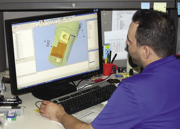
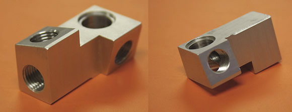
Manufacturing Engineer Chuck Cain uses ESPRIT CAM software to program parts, such as an adapter to connect the pressure and return oil flow from the pump to the desired rescue tool (bottom image), for Holmatro’s products.
The company elected instead to move the part to a lathe with a milling spindle, so Cain reprogrammed the part. ESPRIT made this easy because it can generate the complex code that’s required when integrating milling and turning operations, Cain said. “In this case, we also utilized a 4th axis to do the A-axis index machining.”
By eliminating the investment in an A-axis indexer, the company also avoided additional part handling. “Every time you touch a part in a machine shop, you stand a chance of losing accuracy,” Cain said.
Moving the part to the lathe enabled the shop to use round instead of square bar stock, Cain added. This eliminated having a worker saw 300 slugs about 68mm long for each run. “He was there a long time handling that job,” he said. “Now, we cut the stock into 4 '-long round bars and just put them in the bar feeder.”
Holmatro had to buy a soft collet, purchased for $300 from MicroCentric, for the second operation, milling, because the bar was not round after turning.
With this improved approach, Holmatro produces 32 pump coupling adapters during the day and 95 at night unattended, enabling a 3-minute reduction in cycle time and an overall 296 percent increase in production. Cain estimates Holmatro runs the job at least once a month and saves about $5,200 annually as a result of the change.
When the ultimate task at hand is saving lives, efficiency has a whole new meaning. “We always want to make sure we provide w
Related Glossary Terms
- chuck
chuck
Workholding device that affixes to a mill, lathe or drill-press spindle. It holds a tool or workpiece by one end, allowing it to be rotated. May also be fitted to the machine table to hold a workpiece. Two or more adjustable jaws actually hold the tool or part. May be actuated manually, pneumatically, hydraulically or electrically. See collet.
- collet
collet
Flexible-sided device that secures a tool or workpiece. Similar in function to a chuck, but can accommodate only a narrow size range. Typically provides greater gripping force and precision than a chuck. See chuck.
- computer-aided manufacturing ( CAM)
computer-aided manufacturing ( CAM)
Use of computers to control machining and manufacturing processes.
- gang cutting ( milling)
gang cutting ( milling)
Machining with several cutters mounted on a single arbor, generally for simultaneous cutting.
- lathe
lathe
Turning machine capable of sawing, milling, grinding, gear-cutting, drilling, reaming, boring, threading, facing, chamfering, grooving, knurling, spinning, parting, necking, taper-cutting, and cam- and eccentric-cutting, as well as step- and straight-turning. Comes in a variety of forms, ranging from manual to semiautomatic to fully automatic, with major types being engine lathes, turning and contouring lathes, turret lathes and numerical-control lathes. The engine lathe consists of a headstock and spindle, tailstock, bed, carriage (complete with apron) and cross slides. Features include gear- (speed) and feed-selector levers, toolpost, compound rest, lead screw and reversing lead screw, threading dial and rapid-traverse lever. Special lathe types include through-the-spindle, camshaft and crankshaft, brake drum and rotor, spinning and gun-barrel machines. Toolroom and bench lathes are used for precision work; the former for tool-and-die work and similar tasks, the latter for small workpieces (instruments, watches), normally without a power feed. Models are typically designated according to their “swing,” or the largest-diameter workpiece that can be rotated; bed length, or the distance between centers; and horsepower generated. See turning machine.
- machining center
machining center
CNC machine tool capable of drilling, reaming, tapping, milling and boring. Normally comes with an automatic toolchanger. See automatic toolchanger.
- milling
milling
Machining operation in which metal or other material is removed by applying power to a rotating cutter. In vertical milling, the cutting tool is mounted vertically on the spindle. In horizontal milling, the cutting tool is mounted horizontally, either directly on the spindle or on an arbor. Horizontal milling is further broken down into conventional milling, where the cutter rotates opposite the direction of feed, or “up” into the workpiece; and climb milling, where the cutter rotates in the direction of feed, or “down” into the workpiece. Milling operations include plane or surface milling, endmilling, facemilling, angle milling, form milling and profiling.
- sawing machine ( saw)
sawing machine ( saw)
Machine designed to use a serrated-tooth blade to cut metal or other material. Comes in a wide variety of styles but takes one of four basic forms: hacksaw (a simple, rugged machine that uses a reciprocating motion to part metal or other material); cold or circular saw (powers a circular blade that cuts structural materials); bandsaw (runs an endless band; the two basic types are cutoff and contour band machines, which cut intricate contours and shapes); and abrasive cutoff saw (similar in appearance to the cold saw, but uses an abrasive disc that rotates at high speeds rather than a blade with serrated teeth).
- turning
turning
Workpiece is held in a chuck, mounted on a face plate or secured between centers and rotated while a cutting tool, normally a single-point tool, is fed into it along its periphery or across its end or face. Takes the form of straight turning (cutting along the periphery of the workpiece); taper turning (creating a taper); step turning (turning different-size diameters on the same work); chamfering (beveling an edge or shoulder); facing (cutting on an end); turning threads (usually external but can be internal); roughing (high-volume metal removal); and finishing (final light cuts). Performed on lathes, turning centers, chucking machines, automatic screw machines and similar machines.
Author

Alan holds a bachelor’s degree in journalism from Southern Illinois University Carbondale. Including his 20 years at CTE, Alan has more than 30 years of trade journalism experience.