More tips for operating a CNC lathe
Shop Operations Columnist Tom Lipton offers additional tips for operating a CNC lathe in the February 2014 issue of Cutting Tool Engineering magazine.
Following the theme of last month’s column, here are some additional tips and tricks for operating a CNC lathe.
All images courtesy T. Lipton
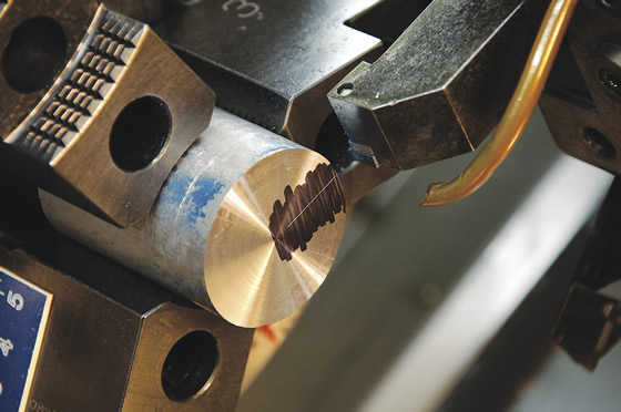
Using a turning tool, scratch a line a tenth or two deep along the turret axis. It allows you to twist a boring bar around and have something for lining up the cutting edge.
■ Try turning off the constant cutting speed when turning tricky plastics. Having manual control over the cutting speed can provide better control of the stringy chips. Chip control in a CNC lathe can be a real roadblock to unattended machining on some types of plastics. You can increase the chip load by slowing the spindle or increasing the feed rate to thicken the chip. Even a simple task like turning off the coolant can sometimes help with chip control.
■ Setting the fine serration top jaws in a CNC lathe power chuck is a common challenge. The 1mm serrations make it easy to set one tooth off and screw up the centering on a blank. Also, it’s difficult to measure three jaws and set them to the middle of the jaw travel. I made special labels that have the basic sizes engraved on them so I can quickly set the jaws to a diameter range and hit all the serrations at the same radius. It cost $5 and a little time to engrave on a mill. Be sure to thoroughly clean the part of the jaws where these labels stick on. Make it a habit to remove the fine jaw serrations from the jaw with a scratch brush when reinstalling the top jaws.
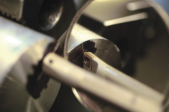
Use a mirror to see a workpiece upside down to align a tool with the scribed centerline.
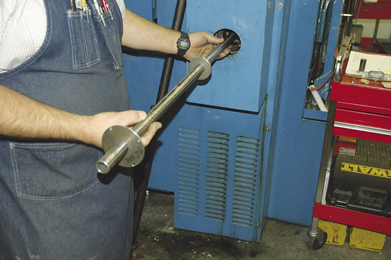
For bar pulling operations, it’s better to have a spindle liner that is close to your raw stock size. Pictured is a simple spindle liner.
Review the print ads from this magazine to continue
This quick advertiser review unlocks the rest of the article and keeps the full-screen reader focused on the ads instead of the page chrome.
Continue reading
February 2014
QR codes and videos from this issue
Print QR codes, video callouts, and in-magazine links for this article now point to the CTE video hub in the HTML version.

MFGAxis Discussion