Minimizing Abbé machine position errors
Two basic strategies exist to minimize the Abbé error in machine tools: eliminate the causes or compensate the result, according to the Machine Technology column in the July 2013…
Understanding and controlling Abbé errors can be crucial when operating machine tools. Named after Ernst Abbé, a 19th century German physicist and former director of research at Zeiss Optical Works, Abbé errors are linear positioning errors caused by a dimensional offset between the location where a position measurement is made and the location of the desired position. This offset amplifies any angular error in the motion.
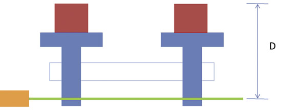
Figure 1 shows a schematic representation of a machine tool table (blue) in two different positions. The workpiece (red) is attached to the top of the table. The table travels along a guide way (white box). As the screw rotates in a fixed nut on the table, the table is driven along the guide way. The screw provides the thrust along the direction of travel, and the guide way normally controls the position perpendicular to the direction of travel.
All images courtesy of S. Smith
Figure 1. Motion of a machine tool table with a straight guide way, where D is the dimensional offset.
In many machine tools, an encoder attached to the screw determines the table position, and the table position is known by measuring the rotation of the screw. Essentially, the table position is measured along the screw axis, but this is not the position of interest. The position of interest is somewhere on the workpiece, say, the center of the top surface. The dimensional offset is indicated in the figure by the letter D. If a guide way is straight and parallel to the screw axis (Figure 1), the motion of the center of the top surface of the workpiece is the same as the motion measured along the screw axis.
However, a guide way is usually not straight or parallel to the screw axis. If a guide way is curved, as shown in an exaggerated way in Figure 2, the motion of the point of interest is different from the measured motion. This difference between measured and desired travel is an Abbé error. The Abbé error increases as the angular error of a guide way increases and as the length of the dimensional offset increases. The magnitude of the Abbé error is the product of the offset and the tangent of the angular error. The equation is offset × tan (angle) = Abbé error. For example, if the offset is 500mm (19.7″), and the angular error is 0.006° (about 22 arc-seconds), the Abbé error is about 0.05mm (about 0.002″).
Review the print ads from this magazine to continue
This quick advertiser review unlocks the rest of the article and keeps the full-screen reader focused on the ads instead of the page chrome.


MFGAxis Discussion