Of the two most common methods of producing internal threads—tapping and thread milling—tapping is by far the more popular.
Mark Hatch, applications specialist at Emuge Corp., a Northborough, Mass., manufacturer of taps and thread mills, estimated that 85 to 90 percent of all internal threads are produced with taps.
Thread milling, however, has begun to narrow the popularity gap. Recent advancements in CNC technology have spurred the growth of the process, which has been around since the 1950s.
Thread milling involves the application of a specially designed milling cutter to machine an internal or external thread. According to Bryan Young, application engineering manager at Mazak Corp., Schaumburg, Ill., most modern CNCs can precisely move a tool in the X, Y and Z axes simultaneously. This 3-axis movement is a process known as helical, or spiral, interpolation. It allows a thread mill to produce highly accurate threads while allowing the operator to precisely control variables that he couldn’t while tapping.

Deciding whether you should tap or thread-mill a hole depends on a number of factors. These include the machine tool used, hole characteristics, material, desired operational flexibility and control, and, of course, cost.
You must analyze all of these factors, determine how significant they are to your process and then choose a course of action. Below are some guidelines to help you with the selection process.
Machine Tool. Start by assessing the capabilities of your machine tool. As Young points out, most of today’s popular 40-taper machining centers lack geared headstocks. This is the result of the market demanding speedier, more accurate, lower-cost machines.
While these machines are generally fast and possess high positional accuracy, their ability to develop adequate torque drops dramatically when spindle speeds fall below 300 rpm—the traditional speeds at which tapping is performed. Upgrading to a geared headstock could cost thousands of dollars and slow nontapping operations.
Thread milling eliminates low-rpm power problems, since it is a milling process. However, CNCs capable of helical interpolation are relatively new. Older CNCs may not be able to perform thread milling, leaving the tapping process as your only viable option.
When tapping or thread milling, experts recommend that you equip your machine tool with a coolant-through-the-spindle system. This is especially important when threading deep holes to ensure that coolant reaches the workpiece/tool interface. If your machine lacks such a system, have one retrofitted by the builder or a third-party supplier.
Another consideration is the long-term effects the chosen process will have on the machine. Thread milling puts no more stress on the machine than conventional milling does. Tapping, though, can wreak havoc on the spindle.
Emuge helped an automobile manufacturer set up a high-volume tapping operation that involved running 20 standard machining centers continually, three shifts a day. The frequent reversing of the spindle that’s required when tapping caused all of the machines’ spindles to fail prematurely. Each had to be rebuilt within 18 months.
The automaker solved the problem by installing self-reversing tapping heads.
Hole Characteristics. The next area to consider is the hole you intend to thread. Dan Gajdosik, engineering manager at tap manufacturer Besly Products Corp., South Beloit, Ill., recommends tapping any hole up to 4" in diameter. He said that while taps tend to be less forgiving and more problematic than thread mills, he believes that they can be more consistent and cost-effective on long runs once the process is brought under control.
Emuge’s Hatch disagreed. He said that thread milling is cost-effective for many applications, including some high-volume runs.
Thread depth and the required configuration at the bottom of the hole also can affect whether you tap or thread-mill. The vice president of Lake Bluff, Ill.-based Advent Tool & Manufacturing Inc., Jim Hartford, said thread mills are only practical at depths that satisfy the 3-1 ratio rule: Thread depth is limited to three times the major thread diameter.
Another consideration is whether you’re threading a through hole or a blind hole. In a tapping operation, there needs to be clearance at the bottom of the hole for the tool’s cutting edge (chamfer). A tap cannot thread the entire hole depth, due to its chamfered cutting edge.
According to Hartford, this is not a problem for a thread mill, which leaves only a slight undercut at the hole’s bottom.
Material. Standard taps begin to encounter problems when cutting materials hardened above RC 30 and in production situations if the material has inconsistencies, such as hard spots. Standards can snap, wear quickly or produce inconsistent thread forms. Using special taps, designed to counter these problems, will increase tool costs.
Thread milling may be the only viable method to effectively cut a thread in difficult-to-machine materials such as Inconel, Invar and Monel. Thread mills also may work better on gummy materials, which can collapse around a tap. That won’t happen with a thread mill, because it doesn’t fully engage the workpiece.
Operational Flexibility and Control. When it comes to flexibility, thread mills have an edge over taps. According to Hatch, only minor programming changes are required for a single 1/2-20 thread mill to thread a range of hole diameters—up to 7/8-20. The same tool can also produce UNC, UNF and UNEF threads. This flexibility lowers tool costs and changeover times and frees up pockets in the toolchanger.
The inherent control that thread milling offers can also lower your scrap rate. If you snap a tap during a high-volume production run, the part might be salvaged or scrapped at a tolerable cost. However, if you are in the final steps of threading holes in an aerospace part with 1,500 hours into it, the risk of scrap can be a critical factor in choosing a thread mill over a comparable tap.
The president of Fulton Precision Industries, Walt Barmont, said that his McConnellsburg, Pa., job shop usually generates threads with taps. Occasionally, though, he opts for thread milling because of the extra control and flexibility that the operation provides.
He takes advantage of the ability to make size adjustments to a thread mill when threading a part that’s been distorted during heat treatment or to make a size allowance for a thread that has to be plated. Barmont said that this capability saves him from having to purchase special taps.
Barmont also discussed a downside to thread milling: It takes longer. In one application, he thread-milled a 1˝-12 hole that was 2" deep. He ended up with a high-quality thread, but the thread mill had to make four passes to complete the thread form. Barmont said that the cycle time was 25 to 30 percent longer than if he had tapped the hole.
When comparing dimensional accuracy, taps and thread mills can both produce threads that will conform to design requirements. In high-accuracy situations, though, it’s hard for a tap to compete with a thread mill.
Hatch said that a standard quick-change tap/holder combination will hold a tolerance of ±0.0050". A solid holder tightens the tolerance to ±0.0020". A typical thread mill, however, can meet a tolerance of ±0.0005". That’s similar to the results possible with a boring bar.
Cost. Aside from the relative operational advantages of one process over another, many times a decision boils down to cost. The table below compares the average cost and performance of a 3/8-24 thread mill and two types of taps.
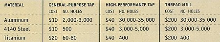
The general-purpose tap is made of HSS. The high-performance tap is coated. In this example, a chromium nitride coating is specified for tapping aluminum and a titanium nitride coating is specified for the steel and titanium applications.
Notice that the hole count does not change significantly between the high-performance tap and the thread mill. Therefore, your decision about whether to tap or thread-mill will probably be based on other variables, such as setup time, tool-pocket limitations, cycle time and hole characteristics.
Taps cost anywhere from $12.37 for a 0-80 tool made of HSS to $1,500 for a 4˝-8 with a TiN coating. Thread mills run from about $200 for a 10-32 tool up to several hundred dollars for a 4˝-8.
An advantage offered by some larger thread mills—those designed for hole diameters of 3/4" or larger—is that they incorporate replaceable inserts. You can run several sizes of a particular pitch by making a programming change, or you can vary thread characteristics by switching to a different type of insert.
Besly’s Gajdosik pointed out that tap resharpening needs to be factored into the total cost of tapping. This expense must be weighed against the cost of inserts for thread mills (above 3/4") vs. the quantity of backup taps needed to keep production running while tools are resharpened.
The decision to tap or thread-mill depends on the variables mentioned above, as well as others. You will have to do some homework before deciding which method is better for a specific threading application.
With the growing sophistication of coatings and CNC technology, you have more options and flexibility than ever before. This flexibility can help you pick the best machine and tool to thread a variety of holes in a myriad of materials.
Related Glossary Terms
- boring
boring
Enlarging a hole that already has been drilled or cored. Generally, it is an operation of truing the previously drilled hole with a single-point, lathe-type tool. Boring is essentially internal turning, in that usually a single-point cutting tool forms the internal shape. Some tools are available with two cutting edges to balance cutting forces.
- boring bar
boring bar
Essentially a cantilever beam that holds one or more cutting tools in position during a boring operation. Can be held stationary and moved axially while the workpiece revolves around it, or revolved and moved axially while the workpiece is held stationary, or a combination of these actions. Installed on milling, drilling and boring machines, as well as lathes and machining centers.
- centers
centers
Cone-shaped pins that support a workpiece by one or two ends during machining. The centers fit into holes drilled in the workpiece ends. Centers that turn with the workpiece are called “live” centers; those that do not are called “dead” centers.
- clearance
clearance
Space provided behind a tool’s land or relief to prevent rubbing and subsequent premature deterioration of the tool. See land; relief.
- computer numerical control ( CNC)
computer numerical control ( CNC)
Microprocessor-based controller dedicated to a machine tool that permits the creation or modification of parts. Programmed numerical control activates the machine’s servos and spindle drives and controls the various machining operations. See DNC, direct numerical control; NC, numerical control.
- conventional milling ( up milling)
conventional milling ( up milling)
Cutter rotation is opposite that of the feed at the point of contact. Chips are cut at minimal thickness at the initial engagement of the cutter’s teeth with the workpiece and increase to a maximum thickness at the end of engagement. See climb milling.
- coolant
coolant
Fluid that reduces temperature buildup at the tool/workpiece interface during machining. Normally takes the form of a liquid such as soluble or chemical mixtures (semisynthetic, synthetic) but can be pressurized air or other gas. Because of water’s ability to absorb great quantities of heat, it is widely used as a coolant and vehicle for various cutting compounds, with the water-to-compound ratio varying with the machining task. See cutting fluid; semisynthetic cutting fluid; soluble-oil cutting fluid; synthetic cutting fluid.
- gang cutting ( milling)
gang cutting ( milling)
Machining with several cutters mounted on a single arbor, generally for simultaneous cutting.
- high-speed steels ( HSS)
high-speed steels ( HSS)
Available in two major types: tungsten high-speed steels (designated by letter T having tungsten as the principal alloying element) and molybdenum high-speed steels (designated by letter M having molybdenum as the principal alloying element). The type T high-speed steels containing cobalt have higher wear resistance and greater red (hot) hardness, withstanding cutting temperature up to 1,100º F (590º C). The type T steels are used to fabricate metalcutting tools (milling cutters, drills, reamers and taps), woodworking tools, various types of punches and dies, ball and roller bearings. The type M steels are used for cutting tools and various types of dies.
- interpolation
interpolation
Process of generating a sufficient number of positioning commands for the servomotors driving the machine tool so the path of the tool closely approximates the ideal path. See CNC, computer numerical control; NC, numerical control.
- milling
milling
Machining operation in which metal or other material is removed by applying power to a rotating cutter. In vertical milling, the cutting tool is mounted vertically on the spindle. In horizontal milling, the cutting tool is mounted horizontally, either directly on the spindle or on an arbor. Horizontal milling is further broken down into conventional milling, where the cutter rotates opposite the direction of feed, or “up” into the workpiece; and climb milling, where the cutter rotates in the direction of feed, or “down” into the workpiece. Milling operations include plane or surface milling, endmilling, facemilling, angle milling, form milling and profiling.
- milling cutter
milling cutter
Loosely, any milling tool. Horizontal cutters take the form of plain milling cutters, plain spiral-tooth cutters, helical cutters, side-milling cutters, staggered-tooth side-milling cutters, facemilling cutters, angular cutters, double-angle cutters, convex and concave form-milling cutters, straddle-sprocket cutters, spur-gear cutters, corner-rounding cutters and slitting saws. Vertical cutters use shank-mounted cutting tools, including endmills, T-slot cutters, Woodruff keyseat cutters and dovetail cutters; these may also be used on horizontal mills. See milling.
- milling machine ( mill)
milling machine ( mill)
Runs endmills and arbor-mounted milling cutters. Features include a head with a spindle that drives the cutters; a column, knee and table that provide motion in the three Cartesian axes; and a base that supports the components and houses the cutting-fluid pump and reservoir. The work is mounted on the table and fed into the rotating cutter or endmill to accomplish the milling steps; vertical milling machines also feed endmills into the work by means of a spindle-mounted quill. Models range from small manual machines to big bed-type and duplex mills. All take one of three basic forms: vertical, horizontal or convertible horizontal/vertical. Vertical machines may be knee-type (the table is mounted on a knee that can be elevated) or bed-type (the table is securely supported and only moves horizontally). In general, horizontal machines are bigger and more powerful, while vertical machines are lighter but more versatile and easier to set up and operate.
- pitch
pitch
1. On a saw blade, the number of teeth per inch. 2. In threading, the number of threads per inch.
- tap
tap
Cylindrical tool that cuts internal threads and has flutes to remove chips and carry tapping fluid to the point of cut. Normally used on a drill press or tapping machine but also may be operated manually. See tapping.
- tapping
tapping
Machining operation in which a tap, with teeth on its periphery, cuts internal threads in a predrilled hole having a smaller diameter than the tap diameter. Threads are formed by a combined rotary and axial-relative motion between tap and workpiece. See tap.
- threading
threading
Process of both external (e.g., thread milling) and internal (e.g., tapping, thread milling) cutting, turning and rolling of threads into particular material. Standardized specifications are available to determine the desired results of the threading process. Numerous thread-series designations are written for specific applications. Threading often is performed on a lathe. Specifications such as thread height are critical in determining the strength of the threads. The material used is taken into consideration in determining the expected results of any particular application for that threaded piece. In external threading, a calculated depth is required as well as a particular angle to the cut. To perform internal threading, the exact diameter to bore the hole is critical before threading. The threads are distinguished from one another by the amount of tolerance and/or allowance that is specified. See turning.
- titanium nitride ( TiN)
titanium nitride ( TiN)
Added to titanium-carbide tooling to permit machining of hard metals at high speeds. Also used as a tool coating. See coated tools.
- titanium nitride ( TiN)2
titanium nitride ( TiN)
Added to titanium-carbide tooling to permit machining of hard metals at high speeds. Also used as a tool coating. See coated tools.
- tolerance
tolerance
Minimum and maximum amount a workpiece dimension is allowed to vary from a set standard and still be acceptable.
- toolchanger
toolchanger
Carriage or drum attached to a machining center that holds tools until needed; when a tool is needed, the toolchanger inserts the tool into the machine spindle. See automatic toolchanger.
- undercut
undercut
In numerical-control applications, a cut shorter than the programmed cut resulting after a command change in direction. Also a condition in generated gear teeth when any part of the fillet curve lies inside of a line drawn tangent to the working profile at its point of juncture with the fillet. Undercut may be deliberately introduced to facilitate finishing operations, as in preshaving.