Last month, I discussed how the combustion shop at Savannah Machinery Works plans to move from batch processing to machining parts one at a time, which in lean terminology is called “single-piece part flow.” This month, I explain how we are implementing the process.
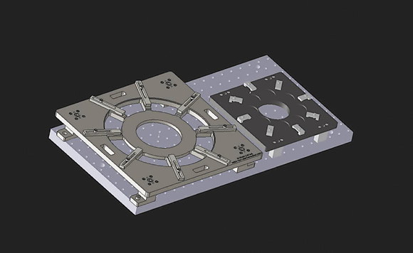
SMW’s subplate, along with two fixtures, in a possible arrangement. The locating dowels are in the lower-left corner, adjacent to the holes used for bolting the fixture in place. This model would be used to create the CNC program.
Off-the-shelf workholding, such as chucks and vises, have allowed our group to be flexible and develop machining processes without having to wait 8 to 10 weeks for a dedicated fixture to be designed and built. However, the off-the-shelf fixtures are not repeatable enough to use on a daily basis in single-piece flow, as they often require the operator to remachine jaws, execute trial cuts and make other time-consuming adjustments to prepare the part run. As a result, we are transitioning to dedicated fixtures as we implement single-piece flow.
Time spent on setup is easier to justify when running batch production, but in single-piece flow it must be reduced. In a single-piece system, setup time is actually cycle time because you cannot amortize the time over a batch of parts.
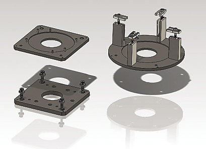
In this receiver plate and fixture plate arrangement, the lower-left image shows the receiver plate bolted to the machine subplate. The two upper images depict the fixture plates attached to the part. The fixture plates travel with the part and interface with receiver plates mounted on multiple machines.
Dedicated fixtures allow operators to set up and run jobs in a matter of minutes. Each machined part will be partnered with a dedicated fixture that will interface with subplates and tombstones. We purchased these elements at the time we acquired our machine tools because we knew quick changeover would be necessary as production volumes increased.
Our machining centers will have a common pattern of 5⁄8 "-dia. bushed holes. The main advantage of a common mounting system is the ability to use the fixtures on any machine in the shop, which reduces bottlenecks and makes scheduling easier.
Locating holes in the tombstones and subplates are lined with drill bushings, and the fixtures have corresponding dowel pins. The pins are inserted into the bushings that align them to the tombstone or subplate. This arrangement allows for quick fixture changes without alignment.
Each row of holes on the tombstones and subplates is identified with a number and each column is identified with a letter, creating a machine table map. This map will be in our CAM software system to synchronize the part program and the machine tool. The map allows the manufacturing engineer to tell the machine operator where on the table the fixture should be placed. This eliminates the need to reset the machining origin each time the fixture is used.
Each fixture will include a hole, a machined corner or a tooling ball that will be an origin for the program. The datum feature allows us to use machine tool probes to set work offsets for the program.
Having a datum on the fixture along with the mapped table may seem redundant, but the datum also allows us to verify that the fixture has been installed correctly. For example, if the fixture is accurately located, we can probe for the datum that should be in the same place in every installation. If the datum is not where it should be, the program stops and an error message that the fixture is out of place is sent to the operator. This should reduce potential for machine crashes.
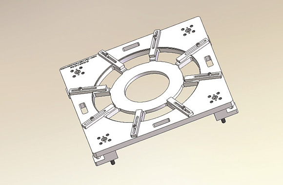
This fixture is for holding a large circular workpiece.
The mapping system will allow us to put multiple fixtures and parts on the same table so part families can be produced simultaneously. We expect that fixtures will always be run in the same position. However, if we need to change locations on the table to accommodate a different arrangement, or, if the fixture is moved to a different machine, we can update the CNC code to reflect the new location.
In some cases, our parts require multiple machining operations on different machines. In these cases, we will mount a fixture plate to the part that will travel with it without being removed from the fixture. The fixture plate will interface with a receiver plate and ball locks will clamp the two fixture plates to the receiver plate. There will be multiple modular receiver plates that interface with the subplates and tombstones.
Our intention is to place the fixture on the table and, without intervention, run a good part. After the part is completed, we will install a fixture for the next part in the schedule and run the new part in the same manner. Cycle times are rarely less than 30 minutes, which means with good planning and capable single-piece part flow processes, our machinists should be able to simultaneously produce parts on multiple machines. Most importantly, we will have scheduling flexibility because we can direct parts to multiple machines and not wait for large batches of parts to be completed before starting the next part.
Implementation is scheduled for June, when the first sets of dedicated fixtures arrive. CTE
About the Author: Christopher Tate is manufacturing engineering lead for machining at Mitsubishi Power Systems, Savannah (Ga.) Machinery Works, a global builder of gas and steam turbines. He has 19 years of experience in the metalworking industry and holds a Master of Science and Bachelor of Science from Mississippi State University. Contact him by e-mail at [email protected].Related Glossary Terms
- centers
centers
Cone-shaped pins that support a workpiece by one or two ends during machining. The centers fit into holes drilled in the workpiece ends. Centers that turn with the workpiece are called “live” centers; those that do not are called “dead” centers.
- computer numerical control ( CNC)
computer numerical control ( CNC)
Microprocessor-based controller dedicated to a machine tool that permits the creation or modification of parts. Programmed numerical control activates the machine’s servos and spindle drives and controls the various machining operations. See DNC, direct numerical control; NC, numerical control.
- computer-aided manufacturing ( CAM)
computer-aided manufacturing ( CAM)
Use of computers to control machining and manufacturing processes.
- fixture
fixture
Device, often made in-house, that holds a specific workpiece. See jig; modular fixturing.
- metalworking
metalworking
Any manufacturing process in which metal is processed or machined such that the workpiece is given a new shape. Broadly defined, the term includes processes such as design and layout, heat-treating, material handling and inspection.
Author

Christopher Tate is the owner of Tate Engineering, a Natchez, Mississippi, firm that helps manufacturers solve efficiency problems. Tate, who earned master's degree in industrial technology from Mississippi State University, has 32 years of experience in the metalworking industry.