High anxiety: Drilling Performance
Understanding tool geometry and selecting the right tap for different workpiece materials can help take the anxiety out of tapping operations.
Many machinists have learned to dread tapping. The story goes something like this. They press cycle start and then step back because the machine is in control. If the tap should hit bottom, too bad; the cycle must be completed—no feed-hold is allowed here. If the wrong feed rate was programmed, tough luck; the feed rate override is disabled. What else is there to do but cringe as the tap enters the hole?
That’s one of the reasons tapping causes anxiety among CNC machine operators. That anxiety leads operators to take many precautions to assure the tap will complete its job of cutting an internal thread.
Other factors can fuel tapping anxiety. Feed rates are typically much higher than for most other cutting tools. With each revolution of the tap, the tool needs to advance one thread pitch. As an example, a 5⁄16-18 tap feeds at 1 divided by 18, or 0.055 ipr. The 0.257-dia. drill that created the hole might feed closer to 0.005 ipr.
It is quite common to tap at slower speeds to “feel” more in control. Slowing the spindle speed is the only way to effectively slow the feed into the hole. A 5⁄16-18 tap cutting at a spindle speed of 900 rpm would feed at 50 ipm, but at 720 rpm the feed would be only 40 ipm.
Understanding Tap Geometry
However, while tapping can be tricky, it is not beyond understanding. Tapping problems can be simplified and reduced by understanding tool geometry and what taps are best suited for a given application.
For example, lowering the chip load can eliminate premature wear on a tap. Defined as the load induced on any one cutting edge, chip load is typically controlled by altering the feed rate. As mentioned earlier, this is not possible when tapping but the chip load can be altered through tap selection.
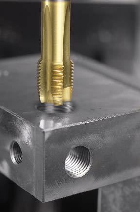
Courtesy of Guhring
Tap with spiral point is shown with a steel part.
One approach might be to use taps with more flutes. With every flute added to the tap, a cutting face is added. With more cutting faces, the load on each tooth is reduced. For example, a 4-flute tap would have half the chip load per tooth of a 2-flute tap. This jives with standard metalcutting advice, which is to always use a maximum number of flutes. However, for tapping this advice would probably be wrong.
“More flutes means there is less space for chips as they are cut,” said David Miskinis, senior application specialist, holemaking for Kennametal Inc., Latrobe, Pa. “More flutes on the same circumference means smaller flutes, both in width and depth. With smaller space comes the risk of packing chips, which can lead to broken taps.”
So, while adding flutes may not be an option, choosing a different chamfer length might be.
“Basically, a longer chamfer length means longer tool life,” said Dr. Peter Haenle, president of Guhring Inc., Brookfield, Wis. “The load during the cutting process is distributed over a longer cutting edge with a lower chip load.”
There are three common lengths of tap chamfers: taper at 7-10 threads, plug at three to five threads and bottoming with one to two threads. To provide more options, tap manufacturers have added a few more forms, including a form consisting of a two- to three-thread length, sometimes called semibottoming.
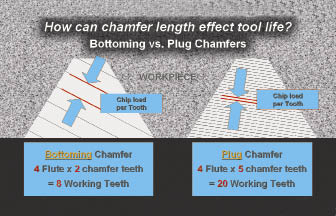
Adding length to the chamfer distributes the chip load over a longer cutting face. Effectively, more teeth are cutting the thread, similar to a single-point threading tool taking multiple passes.
“Chamfer lengths have a huge impact on tap life because they affect chip load,” Miskinis explained. “When comparing chamfer lengths of four threads or fewer, the tool life will double for every half thread added to the length.”
Clearly, increasing chamfer length in taps is desirable. Shorter chamfer lengths, such as in bottoming taps, wear faster and should be avoided, if possible. Unfortunately, there may not always be a choice.
“Taps with smaller chamfer lengths are usually used to keep the difference between hole depth and thread length to a minimum,” Haenle said. “Very often, the design of the part forces the use of taps with short chamfer lengths.”
Courtesy of Kennametal
Another way to tap more effectively is to manage chip thickness. For example, it is possible to thin the chip too much when tapping. Stringy chips can result from using taper chamfers and the tap may create a bird’s nest of chips, preventing lubricant from reaching the tool and chips from properly evacuating. As in other types of machining operations, increasing chip load can help break the chips.
Tap breakage is another issue that creates anxiety among machinists. The saying goes that it’s not the fall that kills you, it’s the sudden stop. But in tapping, it’s not the sudden reversal that causes taps to break, it’s the chips clogging the tool flutes. In some cases, this means chips are packed so tightly so that newly formed chips simply have no place to go, and the tap breaks from the stress.
Tackling Flute Clogging
Even if chips don’t pack so tightly that the tap breaks, flute clogging keeps lubricant away from the tool/workpiece interface and the friction of the chips on the tap creates excessive heat. Chip flow is a critical part of successful tapping. Which direction the chips should move is a factor of the type of hole to be tapped: through or blind. A spiral-flute tap lifts chips out of a blind-hole. The helical angle directs chips out of the hole.
The spiral flute can be referred to as slow, with 15° to 30° helical angles, or fast, with 40° to 60° angles. Faster spirals have a freer-cutting geometry, while slower spirals have a stronger cutting edge. Typically, fast spirals are for softer workpiece materials or materials that produce stringy chips, while slow spirals are for short-chipping, harder materials.
A spiral-point, or gun, tap pushes the chips ahead of the tap when tapping a through-hole. The spiral point itself is actually a left-handed spiral, ground only at the point of the tap, which creates a downward flow of chips. Otherwise, a spiral-point tap looks like a straight-flute hand tap.
Because the flutes of spiral point taps are not actually needed for chip evacuation and are instead applied to allow lubricant in, they can be shallow. Thus, they permit a larger core and a stronger tap. This also means that spiral-point taps can benefit from additional flutes without the problem of chip packing.
Selecting a Tap
Because tapping is a relatively complex operation, and because there are so many taps to choose from, selecting a tap can seem a daunting task. The main reason there are so many taps is because there are so many work materials. Tap manufacturers tailor tap design to the work material primarily through rake and relief.
The cutting face is that portion of the tap flute located between the major and minor diameter of the thread that cuts, or shears, the workpiece. The rake is the angle of the cutting face compared to a line from the center of the tap to the cutting face at the major diameter.
Review the print ads from this magazine to continue
This quick advertiser review unlocks the rest of the article and keeps the full-screen reader focused on the ads instead of the page chrome.


MFGAxis Discussion