Grading Graphite
Grading Graphite
This report details the results of a test of graphite electrodes. The test compared the performance and machinability of three graphite grades, ranging from an inexpensive coarse grade to a relatively costly ultrafine grade.
Not more than a decade ago, a die-sinker EDM was a manual machine that needed a skilled operator to monitor the burn. Now the machine can be programmed to monitor the burn and make parameter changes automatically, thereby keeping the process stable.
Programming advances in die-sinker-EDM software have helped reduce the number of electrodes needed for each cavity. Orbiting patterns produced by the software decrease the amount of electrode taper. Orbiting electrodes have more uniform wear on the leading edge and the sides of the electrodes. Other programming advances allow the EDM user to select a desired surface finish or a no-wear electrode condition to preserve the electrode. The final EDM results are predictable, reliable, and consistent.
Electrode fabrication has changed with the advent of high-speed machining centers. These machining centers can be programmed to produce identical electrodes with high accuracy and repeatability. The machines can cut with very little pressure, producing one-piece electrodes for cavities that once would have required multiple electrodes due to the number of ribs, slots, and thin walls.
The only constant factor during the last decade of rapid technological advancement has been the graphite electrode materials. The same materials that were used on conventional machining equipment to fabricate electrodes for use on manual EDMs are currently used on high-speed machining centers to fabricate electrodes for use on the latest CNC EDM. With electrode fabrication on high-speed machining centers, however, it's even more important for EDM users to understand how the properties of different graphites influence electrode performance.
Graphite Grades
Graphite electrode materials are classified by their average particle size. These materials are grouped into the five classifications shown in Table 1.
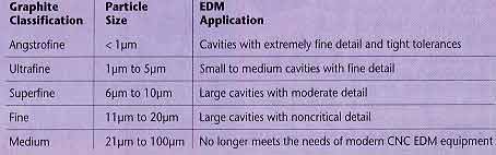
Table 1: Graphite classifications, determined by average particle size, and their EDM applications.
Graphite manufacturers don't expect any new types of graphite to appear on the market. Within each material classification, there are a number of grades produced by different graphite manufacturers. These grades have unique physical properties and microstructures that have been tailored for specific applications.
Physical properties that typically determine the performance of a particular grade are flexural and compressive strength, density, and hardness. The grade's microstructure is also important to the EDM user. Graphite with a consistent grain size, consistent pore size, and uniform particle distribution is harder to produce but offers improved surface finish and electrode wear. The cost of graphite corresponds to the particle-size classification; materials with the largest particle size are the least expensive.
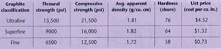
Table 2: Physical properties and list prices of ultrafine, superfine, and fine graphites.
Electrode fabrication on high-speed machining centers has made these physical properties and characteristics even more critical in the selection of a graphite grade. High-speed machining centers make it possible to machine more intricate detail into a lower quality material than would have been possible using manual or CNC machining equipment. By making multiple passes with small chiploads, the machines' high-speed spindles allow thin ribs to be machined without putting pressure on the ribs. Using conventional equipment, materials with low compressive or flexural strength were more likely to break and chip while they were being machined into thin ribs. Using high-speed machining centers, these materials can be machined without problems.
Does this mean that EDM users can use a less expensive, lower quality graphite electrode material and get the same results as they would with a more expensive, higher quality material? EDM users need to consider how the electrode will perform as the cavity is burned.
Electrode Performance
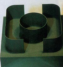
Figure 3: Rough and Finish EDM times achieved by the three graphites at 13 and 21-amp settings.
Materials for thin-rib electrodes should have a flexural strength above 10,000 psi and a compressive strength above 15,000 psi. Graphite grades with these properties are typically found in the angstrofine and ultrafine classifications. Without adequate flexural strength, thin-rib electrodes can be deflected by flushing pressure, or they can break during orbiting. Dense graphite made of small, tightly packed pArticles may be able to resist erosion at the corners and edges of the electrode better than a material with large pArticles and pores can.
EDM users also must remember that even though they can machine detail into an electrode, the electrode's ability to reproduce that detail in the EDMed cavity depends on the physical properties of the electrode material. EDM users may be able to use a less expensive, lower quality material for electrode fabrication, but the increased number of electrodes and the poor quality of the cavity may offset the initial savings.
To determine whether lower quality graphite electrodes can perform as well as higher quality graphite electrodes, the following test was set up by a graphite manufacturer and a machine tool builder. Six electrodes were produced on a high-speed machining center. A roughing and a finishing electrode were made from each of the three most popular graphite classifications: ultrafine, superfine, and fine (Table 2). These six electrodes were used to burn three tool-steel cavities.
Fabrication Results
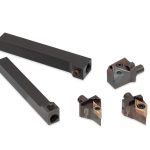
The researchers tested electrodes with a thin-rib design to judge the ability of the materials under machining and EDMing conditions (Figure 1). The electrodes were machined from 4"x4"x2" blocks. The machining program included a roughing sequence of outside profile, inside profile, ID circle, and OD circle, and a finishing sequence of profile, ID circle, and OD circle.
The fine and superfine graphites were run at the following parameters. A 1/2"-dia., 4-flute standard endmill was used to rough machine at 12,000 rpm and 185 ipm. Rough-machining time was 1 minute and 50 seconds. Tool change took 30 seconds. A 1/4"-dia., 2-flute, 50°-helix endmill was used to finish machine at 15,000 rpm and 150 ipm. A high-helix endmill had to be used to prevent chipping of the electrode's rib and a poor surface finish. Finish-machining time was 7 minutes and 10 seconds. Total machining time for each of the four fine and superfine electrodes was 9 minutes and 30 seconds.
Because ultrafine graphite is not as soft as the other two graphites, this material had to be run at 80% of the above speeds and feeds. Rough-machining time for the ultrafine graphite was 2 minutes and 9 seconds, and finish-machining time was 8 minutes and 39 seconds. Total machining time for each of the two ultrafine graphite electrodes, including 30 seconds for tool change, was 11 minutes and 18 seconds.
No problems were encountered during the machining of the graphite blocks from the three graphite classifications. The completed electrodes were almost identical.
EDM Results
To test the performance of the electrode materials in both fine finish burns and aggressive production burns, rough-EDM and finish-EDM burns were planned at two amp settings: burn A at 13 amps and burn B at 21 amps (Table 3). The electrode ribs were 0.020" thick, and the DOC was 1.000". Flushing was not used, because it would cause the electrode to vibrate. Starting at 0.750" DOC, pulsing was used to allow the debris to clear the gap. Both rough-EDM burns were completed before the finish-EDM burns were started.
Ultrafine graphite. By using a fine, 13-amp setting for the rough-EDM burn, it is possible to use the same undersize electrode for the finish-EDM burn, provided that orbiting is always performed. The disadvantage is the length of machining time. Rough-EDM burn A took 11 hours and 22 minutes. A small amount of orbiting was used as this burn was completed to make sure there was enough room for the finishing electrode. For finish-EDM burn A, a 0.0075"-per-side orbit was used to clean up the cavity. Finish-EDM time was 4 hours and 28 minutes.
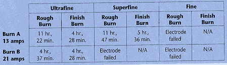
Table 3: Rough-and-finish-EDM times achieved by the three graphites at 13- and 21-amp settings.
A small amount of orbiting also was used as rough-EDM burn B was completed. Rough-EDM time was 4 hours and 37 minutes; this drastic reduction in machining time was due to the higher amp setting. For finish-EDM burn B, a larger finishing electrode with 0.025"-thick ribs was used. A smaller finishing electrode with an orbit of 0.010" per side would cause too much flex, and the cavity probably would not finish to size. Finish-EDM burn B took the same amount of time as finish-EDM burn A did.
In order to save time, the researchers recommend using different undersize electrodes for the rough-EDM and finish-EDM burns. This is important due to the flexing of the electrode material during orbiting. The smaller the orbit, the lower the flex and the shorter the machining time.
Superfine graphite. Rough-EDM burn A took 11 hours and 47 minutes. When rough-EDM burn B was attempted, the electrode broke apart during the burn, and machining was stopped.
Because the electrode had broken during rough-EDM burn B, finish-EDM burn A was expected to be a problem due to the larger amount of orbiting. A larger electrode with 0.025"-thick ribs was used to finish the cavity, but the electrode cracked on the diameter and two small pieces broke off. Finish-EDM burn A took 5 hours and 36 minutes.
The electrodes made from superfine graphite lacked sufficient flexural strength to prevent breakage during orbiting. Different undersize electrodes made from this material may have performed better on a manual EDM without orbiting.
Fine graphite. Rough-EDM burn A took 11 hours and 47 minutes. At the end of the rough-EDM burn, a small amount of orbiting was used to open the slot for the next electrode to drop in without touching the workpiece. When this orbiting pattern started, it broke off the center of the electrode.
Fine graphite at this thickness will yield poor results with little chance of success. The electrode will not orbit without breaking. It may be possible to attempt this kind of burn using a manual EDM, but the chance of success is still minimal.
Each material performed as expected. Graphite from all three classifications was very easy to machine into the desired electrode shape. The differences in physical properties and EDM characteristics were very apparent in the performance of these materials. The ultrafine graphite, with its smaller particle size and higher strength, produced cavities without the electrode failing. Although this graphite has a higher cost, EDM users will achieve consistent results by using the optimal electrode material for their specific EDM application.
About the Author
Jimmy Sherman is senior applications engineer with Poco Graphite Inc., a Unocal company, Decatur, TX.