Monitoring and controlling the spark gap between the EDM wire and workpiece.
The spark gap is the physical distance the electric current has to jump off the wire to burn the workpiece when wire EDMing. Controlling the spark gap is critical to achieving required part dimensions and surface finishes. Variables that impact the spark gap include the workpiece material and thickness, wire diameter and type, and part tolerance and surface finish requirements.
The wire EDM process is physically unstable because of the constant advancement and retraction of the axes. “Wire EDMing does not have or function with a set feed rate like a milling operation,” said Brian Pfluger, EDM product manager for Makino Inc. at the company’s Auburn Hills, Mich., facility. Wire EDMing requires a combination of small mechanical and, especially, electrical changes to occur thousands of times per second to be stable and consistent, he added. Makino is headquartered in Mason, Ohio.
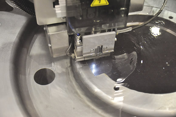
Courtesy of AccuteX EDM
A skim cut being taken on AccuteX EDM’s AX-1160 wire EDM.
If the spark gap is too small for the wire diameter, the spark produces a short circuit, which can damage the workpiece and break the wire. “If the leading edge of the wire gets too close to the material, there is not enough room for ionization and discharge to occur and the wire will typically break,” said Mark Cicchetti, technical director for AccuteX EDM, Mason, Ohio. “There is also not enough room in the gap to evacuate the chips.”
If the spark gap is too large, the electric current will not jump the gap and there will not be any material vaporization.
Machine Control
The development of adaptive controls allows much better control and focus of the spark to get repeatable results.
That control technology senses an unstable condition in the spark gap, Pfluger noted. “It senses if the machine is going too quickly or if the power is too aggressive, then slows down or throttles back on the power to stabilize itself and then advances again.”
There are a variety of ways to slow the machine and make the spark gap more stable. “The two easiest ways common for all machines is adjusting the on-time and off-time,” Pfluger said.
On-time is when the machine is physically burning; off-time is used to flush debris from the spark gap. The adaptive power control makes many small adjustments internally to stabilize wire EDMing by lowering power levels, which will slow the cutting speed. Once stable electrical conditions are reestablished, the control goes on standby and waits to reengage when an electronic circuit integrated with the machine’s power generator detects unstable conditions again.
The Mechanics
Maintaining a stable wire EDM process requires precise mechanical movement. Sodick Inc. offers linear motors on its wire EDMs to help control the spark gap. “To ensure a constant gap, the control system on the machine needs to advance or reverse the axis,” said Dave Thomas, president of Sodick, Schaumburg, Ill. “When using ballscrews to advance or reverse, there is a mechanical delay due to the backlash in the ballscrew. This delay can affect accuracy and cause wire breaks because the machine is not responding to the gap fast enough. In other words, the machine’s electronics and software are capable of sensing a gap condition but the machine cannot respond fast enough due to the ballscrew.”
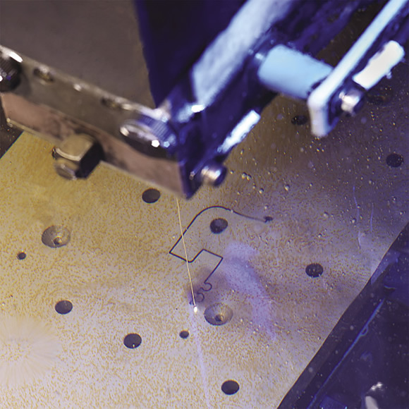
Courtesy of Makino
Machining a D-2 tool steel mold lock on a Makino DUO43 using 0.010 " brass wire.
With linear motors, there is an electronic drive so there is no backlash and no mechanical delay. Therefore, the machine can maintain or respond to gap conditions much faster, according to Thomas.
However, others disagree. “Zero-backlash ballscrew configurations have been available on EDMs for a long time,” said Ken Baeszler, a product manager at GF AgieCharmilles LLC, Lincolnshire, Ill. “Some of these ballscrew machines have servo response times of 3 milliseconds or less, which rivals that of some linear motor machines.”
The Wire Factor
Spark gap size increases as wire diameter increases. Generally, the larger the wire diameter, the faster the cut because it can handle more power than a smaller diameter wire without breaking.
Applying a thin wire can cause problems when EDMing, according to Cicchetti. He considers wire below 0.006 " to be thin, 0.008 " and 0.006 "-dia.wires relatively sturdy, and 0.010 "- and 0.012 "-dia. wires the sturdiest and most commonly used.
“The challenge with thinner wires is increased wire vibration,” he said, adding that gap flushing and even the spark itself can excite a thin wire. “With a thinner wire, you can’t use nearly as much tension to hold the wire taut between the guides as you can with a thicker wire, and the wire starts to whip around. It’s harder to control the spark gap because of that lack of tension.”
Roughing and Skimming
When roughing, the spark gap is large and the spark frequency, or number of sparks per second, is low, but each spark has a high amount of power. Power levels and frequency vary by EDM builder, but a typical gap during roughing ranges from 0.001 " to 0.002 " using 0.010 " or 0.012 " wire. This results in a higher material-removal rate than finishing, or skimming, but provides a rougher surface finish and lower accuracy. The typical surface finish produced by roughing ranges from 90µin. Ra to 125µin. Ra. The produced accuracy from roughing is about 0.001 " using 0.010 " or 0.012 " wire.
Courtesy of GF AgieCharmilles
GF AgieCharmilles’ CUT 1000 can cut with wire as small as 0.0008 " in diameter. The machine is often used for cutting micro parts and features.
In a skim cut, the spark gap is smaller and the spark frequency is higher, but each spark is lower in power. This results in a low mrr, but provides high accuracy and improved surface finishes. The spark gap size during skimming varies based on the total number of programmed finish passes, but a typical range is between 0.0005 " and 0.0001 ". Multiple skim cuts are performed, with each pass using a progressively lower power setting that improves part accuracy and surface finish (see Figure 1 below).
“When skim cutting, the spark gap is critical for part accuracy,” Cicchetti said. “Typically, the shape of a workpiece after roughing is an hourglass; the top and bottom of the cut have a smaller kerf than the middle. On the skim cut, you can change the shape of that vertical wall by how fast or how slow you go and how much energy you are putting on the wire. Maintaining that spark gap is critical on a skim cut to maintain vertical wall straightness.”
First-Class Flushing
The importance of flushing the spark gap cannot be overstated. “If you flush your spark gap well, it decreases the chance of breaking the wire because there are fewer particles,” said GF AgieCharmilles’ Baeszler. Flushing also increases cutting speed because particles aren’t there to obstruct the process.
In addition, flushing pressure is critical. More particles are created during roughing, so the flushing pressure needs to be higher to remove particles as quickly as possible and cool the cutting zone. When skimming, the chips freely fall away, so the dielectric fluid can flow at a lower pressure to prevent wire deflection.
Workpiece shape is also a factor. “With a flat workpiece, the flushing nozzles are closer to the workpiece, ideally within 0.004 ", and therefore almost guarantee a clean gap,” Sodick’s Thomas said. “When the workpiece is not flat, such as a mold cavity, the nozzles cannot be as close, so it becomes harder to keep that gap clean.”
Figure 1. General guidelines for surface finish and part accuracy based on the number of passes using 0.010 " or 0.012 " wire.
|
Number of passes |
Surface finish |
Accuracy |
|
1 Pass |
90µin. Ra to 125µin. Ra |
±0.001" |
|
2 Passes: (1 rough, 1 skim) |
60µin. Ra to 80µin. Ra |
±0.0005" |
|
3 Passes: (1 rough, 2 skim) |
30µin. Ra to 40µin. Ra |
±0.0003" |
|
4 Passes: (1 rough, 3 skim) |
20µin. Ra to 30µin. Ra |
±0.0002" |
|
5 Passes: (1 rough, 4 skim) |
10µin. Ra to 20µin. Ra |
±0.0001" |
Courtesy of Makino
Dielectric fluid is filtered during wire EDMing to minimize the number of particles in the spark gap. Filters are rated in microns by the smallest particle they remove. The type of filter used and its life are based on the workpiece material.
“The particles from aluminum are much larger than other materials, so you have to change the kind of filtration system you are using,” Cicchetti said, noting a standard filter removes particles down to 5µm and has a life of about 100 hours. “With aluminum, you’ll clog that filter in 10 to 15 hours. A 20µm-rated filter would be much more efficient.”
He added that with harder materials like tungsten carbide, the particles are very small. Therefore, the operator can run a slightly smaller spark gap when roughing.
Deionizing resin quality plays an important role. “When wire EDMing, you introduce conductive particles and ‘bad’ ions to the dielectric water and they stay in the water unless removed,” said Baeszler. “Deionizing resin helps maintain the conductivity of the water as defined in the technology parameters. If you don’t change the resin when recommended, it will affect your overcut and create wire breakage.” All wire EDMs have a conductivity probe to indicate when the conductivity of the water has exceeeded the recommended value, he added.
Water or Oil?
The dielectric fluid, which can be water or oil, is also a factor in gap control. The spark gap is smaller when wire EDMing in oil due to the lower conductivity of oil. “Therefore, in some micro-wire applications, a larger diameter wire can be utilized,” Sodick’s Thomas noted.
Oil, however, decreases the cutting speed because it does not allow as much energy to pass through as water, according to Makino’s Pfluger. “There have been advancements to improve the machining speed when using oil, but in a rough cut, where your highest mrr will be found, oil will never be able to meet the same speeds as water and that is based solely on the dielectric characteristics. You cannot pass as much energy through the smaller spark gap of oil.”
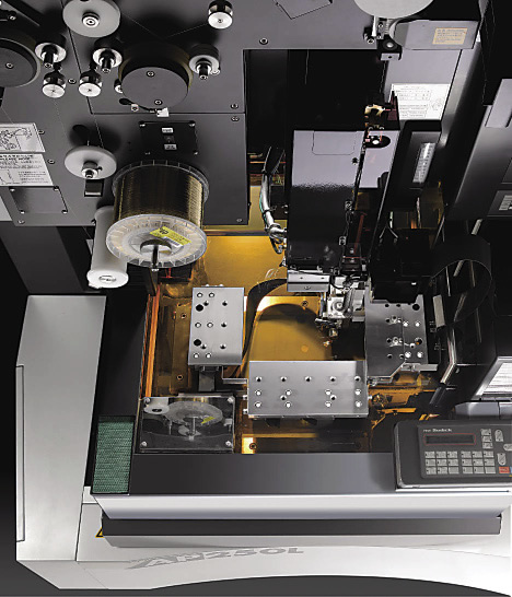
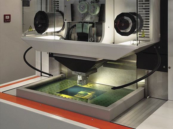
Courtesy of Sodick
Sodick’s AP250L wire EDM using oil dielectric.
But roughing is typically not an application where oil is utilized, according to Thomas. “Oil is selected if accuracy and surface finish are important. The low conductivity level of oil allows finer control of spark energy which reduces the number of passes to achieve the target surface finish and the smaller spark gap enables a closer control of the parts profile for ultimate accuracy.”
Another benefit of oil is found when wire EDMing carbide and PCD. Water chemically attacks and depletes the cobalt binder in those materials, but oil is neutral and does not deplete cobalt.
Also, one nice thing about using dielectric oil is the conductivity stays the same, GF AgieCharmilles’ Baeszler said. “It doesn’t change like with water so there is no need for a resin system.”
Controlling the spark gap when wire EDMing can be a balancing act. Achieving tight tolerances and fine surface finishes is a challenge, but by understanding the variables, EDMers won’t get burned. CTE
About the Author: Susan Woods is a contributing editor for CTE. Contact her at (224) 225-6120 or [email protected].
Contributors
AccuteX EDM
(513) 701-5550
www.accutexedm.com
GF AgieCharmilles LLC
(800) 282-1336
us.gfac.com
Makino Inc.
(800) 552-3288
www.makino.com
Sodick Inc.
(888) 639-2325
www.sodick.com
Related Glossary Terms
- backlash
backlash
Reaction in dynamic motion systems where potential energy that was created while the object was in motion is released when the object stops. Release of this potential energy or inertia causes the device to quickly snap backward relative to the last direction of motion. Backlash can cause a system’s final resting position to be different from what was intended and from where the control system intended to stop the device.
- cutting speed
cutting speed
Tangential velocity on the surface of the tool or workpiece at the cutting interface. The formula for cutting speed (sfm) is tool diameter 5 0.26 5 spindle speed (rpm). The formula for feed per tooth (fpt) is table feed (ipm)/number of flutes/spindle speed (rpm). The formula for spindle speed (rpm) is cutting speed (sfm) 5 3.82/tool diameter. The formula for table feed (ipm) is feed per tooth (ftp) 5 number of tool flutes 5 spindle speed (rpm).
- electrical-discharge machining ( EDM)
electrical-discharge machining ( EDM)
Process that vaporizes conductive materials by controlled application of pulsed electrical current that flows between a workpiece and electrode (tool) in a dielectric fluid. Permits machining shapes to tight accuracies without the internal stresses conventional machining often generates. Useful in diemaking.
- feed
feed
Rate of change of position of the tool as a whole, relative to the workpiece while cutting.
- flat ( screw flat)
flat ( screw flat)
Flat surface machined into the shank of a cutting tool for enhanced holding of the tool.
- gang cutting ( milling)
gang cutting ( milling)
Machining with several cutters mounted on a single arbor, generally for simultaneous cutting.
- kerf
kerf
Width of cut left after a blade or tool makes a pass.
- linear motor
linear motor
Functionally the same as a rotary motor in a machine tool, a linear motor can be thought of as a standard permanent-magnet, rotary-style motor slit axially to the center and then peeled back and laid flat. The major advantage of using a linear motor to drive the axis motion is that it eliminates the inefficiency and mechanical variance caused by the ballscrew assembly system used in most CNC machines.
- milling
milling
Machining operation in which metal or other material is removed by applying power to a rotating cutter. In vertical milling, the cutting tool is mounted vertically on the spindle. In horizontal milling, the cutting tool is mounted horizontally, either directly on the spindle or on an arbor. Horizontal milling is further broken down into conventional milling, where the cutter rotates opposite the direction of feed, or “up” into the workpiece; and climb milling, where the cutter rotates in the direction of feed, or “down” into the workpiece. Milling operations include plane or surface milling, endmilling, facemilling, angle milling, form milling and profiling.
- polycrystalline diamond ( PCD)
polycrystalline diamond ( PCD)
Cutting tool material consisting of natural or synthetic diamond crystals bonded together under high pressure at elevated temperatures. PCD is available as a tip brazed to a carbide insert carrier. Used for machining nonferrous alloys and nonmetallic materials at high cutting speeds.
- tolerance
tolerance
Minimum and maximum amount a workpiece dimension is allowed to vary from a set standard and still be acceptable.
- tungsten carbide ( WC)
tungsten carbide ( WC)
Intermetallic compound consisting of equal parts, by atomic weight, of tungsten and carbon. Sometimes tungsten carbide is used in reference to the cemented tungsten carbide material with cobalt added and/or with titanium carbide or tantalum carbide added. Thus, the tungsten carbide may be used to refer to pure tungsten carbide as well as co-bonded tungsten carbide, which may or may not contain added titanium carbide and/or tantalum carbide.
- wire EDM
wire EDM
Process similar to ram electrical-discharge machining except a small-diameter copper or brass wire is used as a traveling electrode. Usually used in conjunction with a CNC and only works when a part is to be cut completely through. A common analogy is wire electrical-discharge machining is like an ultraprecise, electrical, contour-sawing operation.