END USER: DutchAero BV, 011-31-40-2578-484, www.dutchaero.nl.
CHALLENGE: Confirm toolpath programming is free of errors.
SOLUTION: NC program simulation and verification software.
SOLUTION PROVIDER: CGTech, (949) 753-1050, www.cgtech.com.
DutchAero BV produces aerospace parts at its 2,000-sq.-meter facility in Eindhoven, The Netherlands, with its skilled staff of about 100. The parts include ones for airplane engines made from difficult-to-machine titanium alloys and heat-resistant superalloys, such as Inconel, as well as aluminum structural components.
“Engine parts have steadily increased and now only a small segment of what we machine falls into the structural component category,” said Patrick Delisse, HSM CAM engineer for DutchAero. Some parts have cycle times that cover multiple shifts, such as ones for the Lightning II joint strike fighter’s F136 engine.
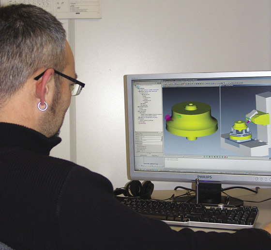
Patrick Delisse, HSM CAM engineer for DutchAero, uses CGTech’s Vericut and OptiPath software to ensure machine tool safety and cutting efficiency.
In addition to the workpiece materials, part complexity has become more challenging for the company. “To produce these parts efficiently, we required more complicated machine tools,” Delisse said. These included a 4-axis Makino machine and a Starrag STC630 machine that can perform simultaneous 5-axis milling.
To confirm error-free programming of the toolpaths to prevent collisions among the machine tool structure, workpiece, workholding fixture and cutting tool, DutchAero needed NC program verification and simulation software. The company selected Vericut from CGTech, Irvine, Calif., because the software is independent of the CAD/CAM system and performs the verification on post-processed NC code.
“The use of Vericut is now mandatory, and no programs are released to the shop floor without first being verified by the software,” Delisse said.
CAD/CAM data comes from DutchAero’s Siemens NX (Unigraphics) software, while Vericut independently verifies and simulates that the toolpaths will run gouge-free and a machine’s axes movements will not cause any collisions.
The latest machines DutchAero installed, a Breton 5-axis mill/turn machine and a Starrag STC 5-axis machine, are used to produce blisks. CGTech’s technical support team provided the virtual model for the Starrag machine tool, complete with details of the CNC system emulation, and the interaction and motion travels of its axes—its kinematics. Breton provided a model of its machine as a Vericut file and Delisse added the control system emulation and machine kinematics.
“We used to do all development in-house, but these days we closely cooperate with suppliers,” Delisse said. “With the functions of a 3-axis machine, generating a model is not too complicated, but for a 5-axis machine it becomes very complicated, so we use the skill and knowledge that CGTech has to provide us with this simulation support.”
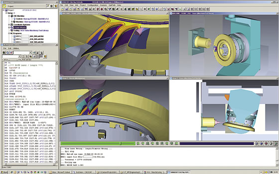
DutchAero simulates and verifies every NC program with Vericut software before sending it to the shop floor.
The company’s Pietro Carnaghi vertical turning lathe is also modeled in the software. Because the lathe can change cutting heads from horizontal to vertical, DutchAero uses the software to correctly orient a cutting tool and simulate any machining operation the lathe performs. The company models the cutting tool assemblies as accurately as possible with WinTool tool management software for use in Vericut. In addition, the verification software can import models from toolmakers that post cutting tool definitions online, such as Sandvik Coromant.
Delisse explained that he uses Vericut interactively on his computer, running the software line by line until it encounters an error, which is then modified before searching for the next error. Then, he restarts the software and runs the program through again to ensure the edited code is free of problems. “I can usually do this overnight,” Delisse said. “When I come in the following day, the code is all correct and can be issued to the shop floor.”
He added that operators view the simulation files so they know what to expect when they run a new job. “With the trust we have in Vericut, we have minimized on-machine prove-outs,” Delisse said. “The only stipulation for the first-part run is an operator and an NC programmer must be present.”
On-machine prove-out is only required when the company evaluates a new workpiece material and conducts a performance test on a new cutting tool technology.
When the cycle time is long because of component complexity or the production volume is high, DutchAero also uses CGTech’s OptiPath cycle-time optimization software, which adjusts cutting parameters to make the machining process more efficient, according to CGTech. Based on the amount of material removed in each segment of the cut, the software inserts improved feed rates where necessary. For example, in a segment requiring light material removal, OptiPath increases the feed rate and then variably decreases the feed as the cutting tool removes more material. Without changing the cutting tool trajectory, the software applies the updated information to a new toolpath.
“Usually, we shave a significant percentage off the cycle times,” Delisse said, adding that even a small reduction is worthwhile on a long-running job.
He also noted that OptiPath NC program optimization software reduces stress on the machine tool structure, extends tool life and improves part surface finish.
Related Glossary Terms
- alloys
alloys
Substances having metallic properties and being composed of two or more chemical elements of which at least one is a metal.
- computer numerical control ( CNC)
computer numerical control ( CNC)
Microprocessor-based controller dedicated to a machine tool that permits the creation or modification of parts. Programmed numerical control activates the machine’s servos and spindle drives and controls the various machining operations. See DNC, direct numerical control; NC, numerical control.
- computer-aided manufacturing ( CAM)
computer-aided manufacturing ( CAM)
Use of computers to control machining and manufacturing processes.
- feed
feed
Rate of change of position of the tool as a whole, relative to the workpiece while cutting.
- fixture
fixture
Device, often made in-house, that holds a specific workpiece. See jig; modular fixturing.
- gang cutting ( milling)
gang cutting ( milling)
Machining with several cutters mounted on a single arbor, generally for simultaneous cutting.
- lathe
lathe
Turning machine capable of sawing, milling, grinding, gear-cutting, drilling, reaming, boring, threading, facing, chamfering, grooving, knurling, spinning, parting, necking, taper-cutting, and cam- and eccentric-cutting, as well as step- and straight-turning. Comes in a variety of forms, ranging from manual to semiautomatic to fully automatic, with major types being engine lathes, turning and contouring lathes, turret lathes and numerical-control lathes. The engine lathe consists of a headstock and spindle, tailstock, bed, carriage (complete with apron) and cross slides. Features include gear- (speed) and feed-selector levers, toolpost, compound rest, lead screw and reversing lead screw, threading dial and rapid-traverse lever. Special lathe types include through-the-spindle, camshaft and crankshaft, brake drum and rotor, spinning and gun-barrel machines. Toolroom and bench lathes are used for precision work; the former for tool-and-die work and similar tasks, the latter for small workpieces (instruments, watches), normally without a power feed. Models are typically designated according to their “swing,” or the largest-diameter workpiece that can be rotated; bed length, or the distance between centers; and horsepower generated. See turning machine.
- milling
milling
Machining operation in which metal or other material is removed by applying power to a rotating cutter. In vertical milling, the cutting tool is mounted vertically on the spindle. In horizontal milling, the cutting tool is mounted horizontally, either directly on the spindle or on an arbor. Horizontal milling is further broken down into conventional milling, where the cutter rotates opposite the direction of feed, or “up” into the workpiece; and climb milling, where the cutter rotates in the direction of feed, or “down” into the workpiece. Milling operations include plane or surface milling, endmilling, facemilling, angle milling, form milling and profiling.
- numerical control ( NC)
numerical control ( NC)
Any controlled equipment that allows an operator to program its movement by entering a series of coded numbers and symbols. See CNC, computer numerical control; DNC, direct numerical control.
- superalloys
superalloys
Tough, difficult-to-machine alloys; includes Hastelloy, Inconel and Monel. Many are nickel-base metals.
- toolpath( cutter path)
toolpath( cutter path)
2-D or 3-D path generated by program code or a CAM system and followed by tool when machining a part.
- turning
turning
Workpiece is held in a chuck, mounted on a face plate or secured between centers and rotated while a cutting tool, normally a single-point tool, is fed into it along its periphery or across its end or face. Takes the form of straight turning (cutting along the periphery of the workpiece); taper turning (creating a taper); step turning (turning different-size diameters on the same work); chamfering (beveling an edge or shoulder); facing (cutting on an end); turning threads (usually external but can be internal); roughing (high-volume metal removal); and finishing (final light cuts). Performed on lathes, turning centers, chucking machines, automatic screw machines and similar machines.
Author

Alan holds a bachelor’s degree in journalism from Southern Illinois University Carbondale. Including his 20 years at CTE, Alan has more than 30 years of trade journalism experience.