Face Off

Author Edmund Isakov, Ph.D.
Published
January 01, 2009 - 11:00am

Keys to maximizing productivity when facemilling steel.

Facemilling during a roughing operation generates a higher metal-removal rate (mrr) than any other type of milling. The mrr indicates the productivity of cutting. Therefore, it is necessary to remove as much material as possible.

The maximum mrr is limited to the nominal machining power and available torque value (at the selected spindle speed) of a given machine tool. Therefore, it is important to calculate the power and torque requirements to achieve the desired mrr. The required machining power should not exceed the nominal power of a given machine tool. In addition, the torque value should not exceed the allowed torque applied to the arbor mounting, and the calculated cutting force should not exceed the force that the cutting edges of the inserts can withstand.

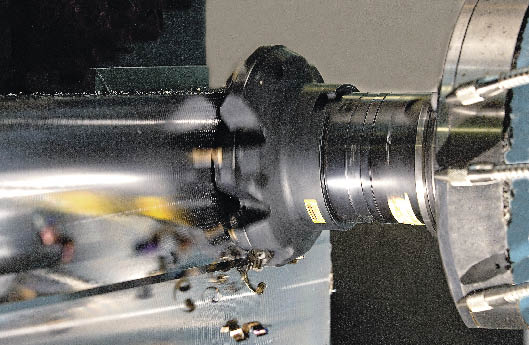
Courtesy of Sandvik Coromant

A CoroMill 345 cutter facemilling steel. The cutter accepts double-sided inserts with eight cutting edges. The tool offers full cutting-edge backing and insert-seat stability through shims with strategic support islands that match insert rake faces. These protect the cutter body should an insert break. By having a more positive axial inclination at small DOCs, the facemill offers a soft cutting action with low axial pressure on the workpiece, according to the company.

This article describes popular cutters for facemilling steel made by Sandvik Coromant Co., Fair Lawn, N.J., and Kennametal Inc., Latrobe, Pa. Calculations of the cutting force, torque and machining power requirements associated with these cutters are based on the tool geometry and the cutting data recommended by the two companies.

The following methods of calculating the required machining power are used for comparison and analysis.

1. The conventional method is based on the unit power values and the mrr as shown in the Machining Data Handbook from Metcut Research Associates Inc., Cincinnati.

2. Calculation methods recommended by Sandvik Coromant, which is based on the specific cutting force (not power), mrr, true rake angle and conversion factor.

3. Calculation method developed by the author and described in his book Engineering Formulas for Metalcutting, from Industrial Press Inc., New York. Kennametal used this method.

Sandvik Coromant Cutter

David Öhlund, milling development specialist, recommended applying the CoroMill 345 cutter and the following cutting data for rough facemilling.

Workpiece: AISI 4140 alloy steel (Coromant Material Classification No. 02.1) with a hardness of 200 HB.

Facemill cutter: catalog item number A345-102R38-13M

Cutter diameter (Dc) = 4.0 "

Number of inserts (Z) = 7

Indexable inserts: catalog item number 345R-1305M-PH

Carbide grade is GC4230 (ISO P25, ANSI C6)

True rake angle (γ) = 11°

Lead angle (κ) = 45°

Cutting Data:

Maximum DOC (ap) = 0.236 "

WOC (ae) = 0.7, or 70 percent of Dc, so ae = 4.0 " × 0.7 = 2.80 "

Feed per tooth (fz) = 0.014 "

Chip thickness (hex) = 0.0099 "

Cutting speed (Vc) = 670 sfm

Kennametal Cutter

Osny Fabricio, senior product manager, global milling, recommended applying Dodeka 45° facemills and the following cutting data for rough facemilling.

Workpiece: AISI 4140 alloy steel (Kennametal Material Group P3/4) with a hardness of 200 HB.

Facemill cutter: catalog item number KSHR400HN5345C5

Cutter diameter (Dc) = 4.0 "

Number of inserts (Z) = 8

Indexable inserts: catalog item number HNGJ535ANSNGD

Carbide grade is KC725M

True rake angle (γ) = 16°

Lead angle (κ) = 45°

Cutting Data:

Maximum DOC (ap) = 0.178 "

WOC (ae) = 0.8 × 4.0 " (Dc) = 3.20 "

Feed per tooth (fz) = 0.011 "

Chip thickness (h) = 0.0079 "

Cutting speed (Vc) = 520 sfm (first-choice starting speed)

Table 1: Type of drive and the efficiency factor.

Type of drive Efficiency factor (%)

Direct drive (integral-motor spindle)

94 to 95

Direct belt drive

90

Back gear drive

75

Geared head drive

70 to 80

Oil-hydraulic drive

60 to 90

Table 2: Comparison between the methods of calculations.

Nomenclature Machining Data Handbook Sandvik Coromant The author’s calculator

Metal removal rate, in.3/min.

41.4

41.4

41.4

Specific cutting force, lbs./in.2

N.A.

246,500

N.A.

Ultimate tensile strength, psi

N.A.

N.A.

100,000

Cutting force, lbs. (sharp cutting edges)

N.A.

N.A

949

Cutting force, lbs. (dull cutting edges)

N.A.

N.A.

1,233

Torque, ft.-lbs. (sharp cutting edges)

N.A.

N.A.

158

Torque, ft.-lbs. (dull cutting edges)

N.A.

N.A.

206

Net power, hp (sharp cutting edges)

N.A.

23.0

19.3

Net power, hp (dull cutting edges)

N.A.

N.A.

25.0

Efficiency factor

0.8

0.8

0.8

Unit power, hp/in.3/min. (sharp tools)

1.1

N.A.

N.A.

Unit power, hp/in.3/min. (dull tools)

1.4

N.A.

N.A.

Required machining power, hp

(sharp cutting edges)

45.5

28.8

24.1

Required machining power, hp

(dull cutting edges)

58.0

N.A.

31.3

Machining Calculations

The following calculations were performed based on the cutting data submitted by Sandvik Coromant and Kennametal.

The mrr (Q) is calculated by the commonly used formula:

Q = ae × ap × fz × Z × n (in.3/min.)

Where n is a spindle speed:

n = 12 × Vc ÷ (π × Dc)

Sandvik Coromant cutter:

Spindle speed,

n = 12 × 670 ÷ (π × 4.0) = 640 rpm

mrr,

Q = 0.236 × 2.8 × 0.014 × 7 × 640 = 41.4 in.3/min.

Kennametal cutter:

Spindle speed,

n = 12 × 520 ÷ (π × 4.0) = 497 rpm

mrr,

Q = 0.178 × 3.2 × 0.011 × 8 × 497 = 24.9 in.3/min.

The required machining power is calculated in two steps. First, the net power, or power at the cutter, is calculated. Then, the required machining power is calculated through the net power and the machine efficiency factor.

The Machining Data Handbook method does not provide a formula for calculating the net power, but allows calculating the required machining power (Pm) from the formula:

Pm = Q × P (hp)

Where P is the unit power.

When milling carbon, alloy and tool steels with a Brinell hardness from 85 to 200 HB at a feed rate from 0.005 to 0.012 ipt, the unit power values are: 1.1 hp/in.3/min. for sharp tools and 1.4 hp/in.3/min. for dull tools. Unfortunately, this handbook does not provide the unit power for a 0.014-ipt feed rate. Therefore, the previous values are used. The unit power values represent an 80 percent machine efficiency factor (η = 0.8). Having Q = 41.4 in.3/min. for the Sandvik Coromant cutter, and Q = 24.9 in.3/min. for the Kennametal cutter, the required machining power values are provided.

Sandvik Coromant Q, sharp tools:

Pm = 41.4 × 1.1 = 45.5 hp

Sandvik Coromant Q, dull tools:

Pm = 41.4 × 1.4 = 58.0 hp

Kennametal Q, sharp tools:

Pm = 24.9 × 1.1 = 27.4 hp

Kennametal Q, dull tools:

Pm = 24.9 × 1.4 = 34.9 hp

Sandvik Coromant customers must have a 50- to 60-hp milling machine if they applied the Machining Data Handbook method, whereas Kennametal customers must have 30- to 35-hp milling machine if they applied the Machining Data Handbook method.

The Sandvik Coromant method recommends the following formula to calculate the net power:

Pn = ae × ap × fz × Z × n × kc × Mγ ÷ 396,000 (hp)

Where ae , ap , fz , Z and n are the values described earlier, kc is the specific cutting force, Mγ is the multiplying factor for true rake angle, and 396,000 in.-lbs./min./hp is the conversion factor.

AISI 4140 alloy steel belongs to No. 02.1 group, according to the Coromant Material Classification (CMC). The specific cutting force of this steel at a Brinell hardness of 175 HB is: kc = 246,500 lbs./in.2, which represents a 5.0 "-dia. cutter and working engagement (ae) of 4.0 ". Because a specific cutting force of the same steel at 200 HB is not provided by the CMC, the same kc value is used to calculate the net power.

If the true rake angle of indexable inserts is 0°, then Mγ = 1. Because the true rake angle of the indexable inserts is γ = 11°, the multiplying factor Mγ = 0.89.

The net power is:

Pn = 2.8 × 0.236 × 0.014 × 7 × 640 × 246,500 × 0.89 ÷ 396,000 = 23.0 hp

The required machining power (Pm) depends on the machine efficiency factor (η) and is calculated from:

Pm = Pn ÷ η

The machine efficiency factors depend on the type of drives (Table 1).

Assuming that the milling machine has the oil-hydraulic drive of 80 percent efficiency factor and A345-102R38-13M cutter with new or just indexed inserts are used, the required machining power would be:

Pm = 23.0 ÷ 0.8 = 28.8 hp

Application of Sandvik Coromant A345-102R38-13M cutters at the recommended cutting conditions requires a 30- to 35-hp machine tool (η = 0.8 to 0.7 respectively). The required machining power could be reduced if a milling machine with higher than an 80 percent efficiency factor is used.

Any machine tool with a 90 percent efficiency factor will consume:

Pm = 23.0 ÷ 0.9 = 25.6 hp

The Author’s Method

The author’s method is based on the concept that the cutting force can be calculated through the ultimate tensile strength of a workpiece material, cross-sectional area of the uncut chip, the number of inserts (teeth) in the cut and the engagement factor, which depends on the ratio of cutter diameter to WOC and the type of work materials. The concept has been proven by numerous cutting tests employing a milling dynamometer. The accuracy in calculating cutting force is about ±20 percent or better. This method is described in Engineering Formulas for Metalcutting.

The net power calculation is based on the cutting force, cutting speed and conversion factor (33,000 ft.-lbs./min./hp), i.e., on the classic formula known in general mechanics for more than 100 years.

The relationship between the ultimate tensile strength of carbon and alloy steels and their Brinell hardness is expressed by a simple and accurate (±5 percent or better) empirical formula:

σ = 500 × Brinell hardness number

Because the hardness of AISI 4140 alloy steel in this case is 200 HB, the ultimate tensile strength is:

σ = 500 × 200 = 100,000 psi

All step-by-step calculations were performed on the author’s Advanced Milling Calculator, but are omitted here due to space limitations. Therefore, only the final results are provided.

Sandvik Coromant Cutting Data

Cutting force (Fc) and torque at the cutter (T) values are:

Fc = 949 lbs., T = 158 ft.-lbs.: A345-102R38-13M cutter with new or just indexed inserts (sharp cutting edges).

Fc = 1,233 lbs., T = 206 ft.-lbs.: A345-102R38-13M cutter, when indexing or replacing of inserts is required (dull cutting edges).

Based on the cutting force values, the net machining power, or power at the cutter, is calculated by the formula:

Pn = Fc × Vc ÷ 33,000 (hp)

Pn = 949 × 670 ÷ 33,000 = 19.3 hp (sharp cutting edges)

Pn = 1,233 × 670 ÷ 33,000 = 25.0 hp (dull cutting edges)

Required machining power (for adequate comparison, a milling machine has the same efficiency factor η = 0.8) is calculated as:

Pm = 19.3 ÷ 0.8 = 24.1 hp (sharp cutting edges)

Pm = 25.0 ÷ 0.8 = 31.3 hp (dull cutting edges)

If the author’s method of calculation is applied to the Sandvik Coromant cutter A345-102R38-13M for rough facemilling at the same cutting conditions described previously, a 30-hp machine would be sufficient. The required machining power could be reduced if a milling machine with higher than an 80 percent efficiency factor is used.

Any machine tool with a 90 percent efficiency factor would consume:

Pm = 19.3 ÷ 0.9 = 21.4 hp (sharp cutting edges)

Pm = 25.0 ÷ 0.9 = 27.8 hp (dull cutting edges)

Cutting parameters for the Sandvik Coromant A345-102R38-13M milling cutter calculated by the three different methods are summarized in Table 2.

Courtesy of Kennametal

A Kennametal Dodeka facemill machining C-45 steel. When in contact with the workpiece, Kennametal says the facemill provides up to 30 percent improvement in cutting performance without increasing power consumption. The cutter accepts inserts with 12 cutting edges. The Dodeka has four different topographies, including a new wiper geometry.

Table 3: Comparison between the methods of calculations.

Nomenclature Machining Data Handbook The author’s calculator

Metal removal rate, in.3/min.

24.9

24.9

Ultimate tensile strength, psi

N.A.

100,000

Cutting force, lbs. (sharp cutting edges)

N.A.

828

Cutting force, lbs. (dull cutting edges)

N.A.

994

Torque, ft.-lbs. (sharp cutting edges)

N.A.

138

Torque, ft.-lbs. (dull cutting edges)

N.A.

166

Net power, hp (sharp cutting edges)

N.A.

13.0

Net power, hp (dull cutting edges)

N.A.

15.7

Efficiency factor

0.8

0.8

Unit power, hp/in.3/min. (sharp tools)

1.1

N.A.

Unit power, hp/in.3/min. (dull tools)

1.4

N.A.

Required machining power, hp (sharp cutting edges)

27.4

16.3

Required machining power, hp ( dull cutting edges)

34.9

19.6

Kennametal Cutting Data

Kennametal uses the author’s method for calculating cutting parameters when facemilling. Final results are based on the cutting data submitted by Osny Fabricio.

Cutting force (Fc) and torque at the cutter (T) values are:

Fc = 828 lbs., T = 138 ft.-lbs.: KSHR400HN5345C5 cutter with new or just indexed inserts (sharp cutting edges).

Fc = 994 lbs., T = 166 ft.-lbs.: KSHR400HN5345C5 cutter, when indexing or replacing of inserts is required (dull cutting edges).

The net machining power, or power at the cutter, is calculated as:

Pn = 828 × 520 ÷ 33,000 = 13.0 hp (sharp cutting edges)

Pn = 994 × 520 ÷ 33,000 = 15.7 hp (dull cutting edges)

Required machining power (for adequate comparison, a milling machine has the same efficiency factor η = 0.8) is calculated as:

Pm = 13.0 ÷ 0.8 = 16.3 hp (sharp cutting edges)

Pm = 15.7 ÷ 0.8 = 19.6 hp (dull cutting edges)

A 20-hp machine would be sufficient for the cutting conditions described earlier. The required machining power could be reduced if a milling machine with higher than an 80 percent efficiency factor is used.

Any machine tool with a 90 percent efficiency factor would consume:

Pm = 13.0 ÷ 0.9 = 14.4 hp (sharp cutting edges)

Pm = 15.7 ÷ 0.9 = 17.4 hp (dull cutting edges)

Cutting parameters for the Kennametal KSHR400HN5345C5 milling cutter calculated by the two different methods are summarized in Table 3.

An end user is able to achieve the highest mrr when rough facemilling compared to other milling operations, but it’s important to accurately calculate the power and torque requirements for a given machine tool to achieve the desired level of productivity. By using the author’s method to perform those calculations, an end user can achieve that level of productivity using a machine tool with less horsepower than when calculating the requirements using the conventional method provided by the Machining Data Handbook. CTE

About the Author: Edmund Isakov, Ph.D., is a consultant and writer. He is the author of several books, including “Engineering Formulas for Metalcutting” (Industrial Press, 2004) and “Cutting Data for Turning of Steel” (Industrial Press, 2009). He can be e-mailed at edmundisakov@bellsouth.net or reached at (561) 369-4063.

Contributors

Kennametal Inc. 
(800) 446-7738
www.kennametal.com

Sandvik Coromant Co.
(800) 726-3845
www.coromant.sanvik.com/us

Related Glossary Terms

  • Brinell hardness number ( HB)

    Brinell hardness number ( HB)

    Number related to the applied load (usually, 500 kgf and 3,000 kgf) and to the surface area of the permanent impression made by a 10mm ball indenter. The Brinell hardness number is a calculated value of the applied load (kgf) divided by the surface area of the indentation (mm2). Therefore, the unit of measure of a Brinell hardness number is kgf/mm2, but it is always omitted.

  • Brinell hardness number ( HB)2

    Brinell hardness number ( HB)

    Number related to the applied load (usually, 500 kgf and 3,000 kgf) and to the surface area of the permanent impression made by a 10mm ball indenter. The Brinell hardness number is a calculated value of the applied load (kgf) divided by the surface area of the indentation (mm2). Therefore, the unit of measure of a Brinell hardness number is kgf/mm2, but it is always omitted.

  • alloy steels

    alloy steels

    Steel containing specified quantities of alloying elements (other than carbon and the commonly accepted amounts of manganese, sulfur and phosphorus) added to cause changes in the metal’s mechanical and/or physical properties. Principal alloying elements are nickel, chromium, molybdenum and silicon. Some grades of alloy steels contain one or more of these elements: vanadium, boron, lead and copper.

  • arbor

    arbor

    Shaft used for rotary support in machining applications. In grinding, the spindle for mounting the wheel; in milling and other cutting operations, the shaft for mounting the cutter.

  • backing

    backing

    1. Flexible portion of a bandsaw blade. 2. Support material behind the cutting edge of a tool. 3. Base material for coated abrasives.

  • cutting force

    cutting force

    Engagement of a tool’s cutting edge with a workpiece generates a cutting force. Such a cutting force combines tangential, feed and radial forces, which can be measured by a dynamometer. Of the three cutting force components, tangential force is the greatest. Tangential force generates torque and accounts for more than 95 percent of the machining power. See dynamometer.

  • cutting speed

    cutting speed

    Tangential velocity on the surface of the tool or workpiece at the cutting interface. The formula for cutting speed (sfm) is tool diameter 5 0.26 5 spindle speed (rpm). The formula for feed per tooth (fpt) is table feed (ipm)/number of flutes/spindle speed (rpm). The formula for spindle speed (rpm) is cutting speed (sfm) 5 3.82/tool diameter. The formula for table feed (ipm) is feed per tooth (ftp) 5 number of tool flutes 5 spindle speed (rpm).

  • dynamometer

    dynamometer

    When drilling, a device for measuring the generated torque and axial force (thrust). When milling, a device for measuring the generated torque and feed force. When turning, a device for measuring the tangential, feed and radial forces.

  • facemill

    facemill

    Milling cutter for cutting flat surfaces.

  • facemilling

    facemilling

    Form of milling that produces a flat surface generally at right angles to the rotating axis of a cutter having teeth or inserts both on its periphery and on its end face.

  • feed

    feed

    Rate of change of position of the tool as a whole, relative to the workpiece while cutting.

  • gang cutting ( milling)

    gang cutting ( milling)

    Machining with several cutters mounted on a single arbor, generally for simultaneous cutting.

  • hardness

    hardness

    Hardness is a measure of the resistance of a material to surface indentation or abrasion. There is no absolute scale for hardness. In order to express hardness quantitatively, each type of test has its own scale, which defines hardness. Indentation hardness obtained through static methods is measured by Brinell, Rockwell, Vickers and Knoop tests. Hardness without indentation is measured by a dynamic method, known as the Scleroscope test.

  • inches per tooth ( ipt)

    inches per tooth ( ipt)

    Linear distance traveled by the cutter during the engagement of one tooth. Although the milling cutter is a multi-edge tool, it is the capacity of each individual cutting edge that sets the limit of the tool, defined as: ipt = ipm/number of effective teeth 5 rpm or ipt = ipr/number of effective teeth. Sometimes referred to as the chip load.

  • lead angle

    lead angle

    Angle between the side-cutting edge and the projected side of the tool shank or holder, which leads the cutting tool into the workpiece.

  • metal-removal rate

    metal-removal rate

    Rate at which metal is removed from an unfinished part, measured in cubic inches or cubic centimeters per minute.

  • metalcutting ( material cutting)

    metalcutting ( material cutting)

    Any machining process used to part metal or other material or give a workpiece a new configuration. Conventionally applies to machining operations in which a cutting tool mechanically removes material in the form of chips; applies to any process in which metal or material is removed to create new shapes. See metalforming.

  • milling

    milling

    Machining operation in which metal or other material is removed by applying power to a rotating cutter. In vertical milling, the cutting tool is mounted vertically on the spindle. In horizontal milling, the cutting tool is mounted horizontally, either directly on the spindle or on an arbor. Horizontal milling is further broken down into conventional milling, where the cutter rotates opposite the direction of feed, or “up” into the workpiece; and climb milling, where the cutter rotates in the direction of feed, or “down” into the workpiece. Milling operations include plane or surface milling, endmilling, facemilling, angle milling, form milling and profiling.

  • milling cutter

    milling cutter

    Loosely, any milling tool. Horizontal cutters take the form of plain milling cutters, plain spiral-tooth cutters, helical cutters, side-milling cutters, staggered-tooth side-milling cutters, facemilling cutters, angular cutters, double-angle cutters, convex and concave form-milling cutters, straddle-sprocket cutters, spur-gear cutters, corner-rounding cutters and slitting saws. Vertical cutters use shank-mounted cutting tools, including endmills, T-slot cutters, Woodruff keyseat cutters and dovetail cutters; these may also be used on horizontal mills. See milling.

  • milling machine ( mill)

    milling machine ( mill)

    Runs endmills and arbor-mounted milling cutters. Features include a head with a spindle that drives the cutters; a column, knee and table that provide motion in the three Cartesian axes; and a base that supports the components and houses the cutting-fluid pump and reservoir. The work is mounted on the table and fed into the rotating cutter or endmill to accomplish the milling steps; vertical milling machines also feed endmills into the work by means of a spindle-mounted quill. Models range from small manual machines to big bed-type and duplex mills. All take one of three basic forms: vertical, horizontal or convertible horizontal/vertical. Vertical machines may be knee-type (the table is mounted on a knee that can be elevated) or bed-type (the table is securely supported and only moves horizontally). In general, horizontal machines are bigger and more powerful, while vertical machines are lighter but more versatile and easier to set up and operate.

  • rake

    rake

    Angle of inclination between the face of the cutting tool and the workpiece. If the face of the tool lies in a plane through the axis of the workpiece, the tool is said to have a neutral, or zero, rake. If the inclination of the tool face makes the cutting edge more acute than when the rake angle is zero, the rake is positive. If the inclination of the tool face makes the cutting edge less acute or more blunt than when the rake angle is zero, the rake is negative.

  • tensile strength

    tensile strength

    In tensile testing, the ratio of maximum load to original cross-sectional area. Also called ultimate strength. Compare with yield strength.

  • tool steels

    tool steels

    Group of alloy steels which, after proper heat treatment, provide the combination of properties required for cutting tool and die applications. The American Iron and Steel Institute divides tool steels into six major categories: water hardening, shock resisting, cold work, hot work, special purpose and high speed.

  • turning

    turning

    Workpiece is held in a chuck, mounted on a face plate or secured between centers and rotated while a cutting tool, normally a single-point tool, is fed into it along its periphery or across its end or face. Takes the form of straight turning (cutting along the periphery of the workpiece); taper turning (creating a taper); step turning (turning different-size diameters on the same work); chamfering (beveling an edge or shoulder); facing (cutting on an end); turning threads (usually external but can be internal); roughing (high-volume metal removal); and finishing (final light cuts). Performed on lathes, turning centers, chucking machines, automatic screw machines and similar machines.

  • wiper

    wiper

    Metal-removing edge on the face of a cutter that travels in a plane perpendicular to the axis. It is the edge that sweeps the machined surface. The flat should be as wide as the feed per revolution of the cutter. This allows any given insert to wipe the entire workpiece surface and impart a fine surface finish at a high feed rate.

Author

Edmund Isakov, Ph.D., is a consultant, writer and frequent CTE contributor. He is the author of the books “Mechanical Properties of Work Materials” (Modern Machine Shop Publications, 2000); “Engineering Formulas for Metalcutting” (Industrial Press, 2004); “Cutting Data for Turning of Steel” (Industrial Press, 2009); the CD-ROM “International System of Units (SI)” (Industrial Press, 2012); and the software “Advanced Metalcutting Calculators” (Industrial Press, 2005). For more information, call (561) 369-4063 or visit www.edmundisakovphd.com. 

Click to view all articles written by Edmund Isakov, PH.D.