Continuing the theme of the previous three columns, here are additional tips for enhancing the operation of a CNC milling machine.
All images courtesy T. Lipton
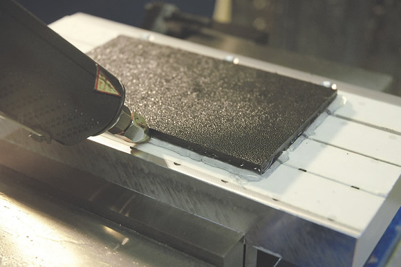
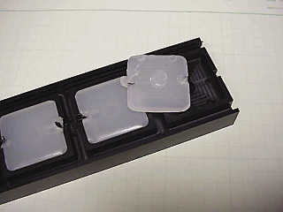
For a little extra resistance to coolant when holding a part with double-stick tape, run a bead of hot wax around the part using a hot glue gun.
■ Double-stick tape can work well for workholding. Only experience will teach you which kinds of parts can be successfully held this way. I use a double-sided tape called “Permacel.” It seems to be more resistant to coolant than some of the other types I’ve tried. For a little extra resistance to coolant, I run a bead of hot wax around the part using a cheap hot-glue gun. This seems to seal out the coolant just long enough to get the job done.

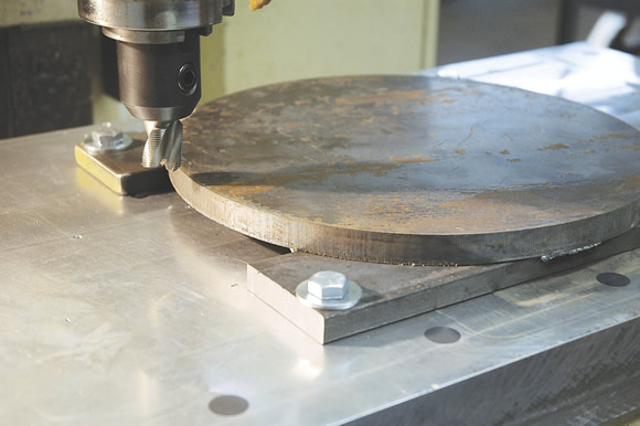
With certain kinds of profiling (above), weld a part to the hold downs without the need for extra holding stock. Welding from the backside (below) also provides a little chip clearance and room for drill penetration under the part.
■ Prepare the base plates carefully when using double-stick tape for best results. I like to dovetail the base plates and surface them all at the same time for an accurate Z-axis position like a set of quick-change miniature pallets. Clean the plates with isopropyl alcohol before applying the tape. Position the blank and then go around the blank perimeter with a C-clamp to seat it firmly into the tape. It’s important to press the blank down into the tape. The holding power of the double-sided tape is all about the amount of surface area it contacts. You can prepare the blanks offline while the first ones are in the machine if you have several base plates. I like to use fresh tape for each part to provide the best chance for success.
■ With certain kinds of profiling, you can weld a part to the hold downs without the need for extra holding stock. Once the profiling is complete, remove the hold-down bars or tabs and surface the second side. This technique keeps the blank thickness close to the finish size, eliminating the large amount of holding stock that makes surfacing the second side an effort. This method works well for open shapes like “C” and “H,” which could be distorted from heavy clamping pressure.
■ All of my CNC mills lack rigid tapping, which makes controlling tapping depth a bit of a challenge. I modified the normal tension and compression holders so they have limited compression length by internally inserting a longer pin. This reduces the compression travel to a third of the stock. This approach, combined with a modest spindle speed, provides good tap-depth accuracy.
■ I have always liked the 10-ipm rule for tapping. Take any tap pitch at 10 ipm and multiply the pitch per inch by 10 to get the spindle speed. For example, a 10-32 tap run at 10 ipm gives 320 rpm (32×10).
■ Even if you have rigid tapping, you might look at a reversing tapping head for your CNC mill. These have the advantage of instantly reversing, whereas the spindle must slow and actually stop when rigid tapping. If you have to tap huge numbers of holes, this approach can reduce the cycle time. Torque control is usually adjustable with the tapping head, unlike rigid tapping holders.
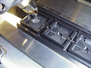
Top: Use hot-melt glue to support a part for secondary operations. Bottom: On most smooth machined surfaces, this glue can be plucked off without leaving a residue. Apply a little spray mold release to make removal even easier.
■ When doing 3-axis contouring with ballnose endmills, a handy trick is to calculate the effective cutting diameter and increase the spindle speed and feed rate to take advantage of this offset. The full diameter of a ball endmill is rarely fully engaged in fine step profiling and surfacing. If the endmill diameter is used to calculate the spindle speed, you are most likely running 50 percent too slow.
■ Try to deburr and finish a part in the machine if possible. The added cycle time can be subtracted from the attended machine time. Use small chamfers on unspecified edge breaks whenever possible. A 45° chamfer is more tolerant of part geometry errors than an equal-sized break using a radius.
■ I’ve been using a trick I learned from a buddy with great results. Use hot-melt glue to support a part for secondary operations. For example, if the part floor is thin and the back was surfaced over the thin floor, chatter results and an unacceptable finish is imparted. By filling and supporting the thin floor with hot glue, the second side comes out flat with an excellent finish. Thin webs, floors and overhangs can be supported with this cheap material. On most smooth machined surfaces, this glue can be plucked off without leaving a residue. Apply a little spray mold release to make removal even easier. Denatured alcohol also helps separate the solidified glue from delicate features. CTE
About the Author: Tom Lipton is a career metalworker who has worked at various job shops that produce parts for the consumer product development, laboratory equipment, medical services and custom machinery design industries. He has received six U.S. patents and lives in Alamo, Calif. For more information, visit his blog at oxtool.blogspot.com and video channel at www.youtube.com/user/oxtoolco. Lipton’s column is adapted from information in his book “Metalworking Sink or Swim: Tips and Tricks for Machinists, Welders, and Fabricators,” published by Industrial Press Inc., New York. The publisher can be reached by calling (888) 528-7852 or visiting www.industrialpress.com. By indicating the code CTE-2013 when ordering, CTE readers will receive a 20 percent discount off the book’s list price of $44.95.
Related Glossary Terms
- chatter
chatter
Condition of vibration involving the machine, workpiece and cutting tool. Once this condition arises, it is often self-sustaining until the problem is corrected. Chatter can be identified when lines or grooves appear at regular intervals in the workpiece. These lines or grooves are caused by the teeth of the cutter as they vibrate in and out of the workpiece and their spacing depends on the frequency of vibration.
- chip clearance
chip clearance
In milling, the groove or space provided in the cutter body that allows chips to be formed by the inserts.
- clearance
clearance
Space provided behind a tool’s land or relief to prevent rubbing and subsequent premature deterioration of the tool. See land; relief.
- computer numerical control ( CNC)
computer numerical control ( CNC)
Microprocessor-based controller dedicated to a machine tool that permits the creation or modification of parts. Programmed numerical control activates the machine’s servos and spindle drives and controls the various machining operations. See DNC, direct numerical control; NC, numerical control.
- coolant
coolant
Fluid that reduces temperature buildup at the tool/workpiece interface during machining. Normally takes the form of a liquid such as soluble or chemical mixtures (semisynthetic, synthetic) but can be pressurized air or other gas. Because of water’s ability to absorb great quantities of heat, it is widely used as a coolant and vehicle for various cutting compounds, with the water-to-compound ratio varying with the machining task. See cutting fluid; semisynthetic cutting fluid; soluble-oil cutting fluid; synthetic cutting fluid.
- endmill
endmill
Milling cutter held by its shank that cuts on its periphery and, if so configured, on its free end. Takes a variety of shapes (single- and double-end, roughing, ballnose and cup-end) and sizes (stub, medium, long and extra-long). Also comes with differing numbers of flutes.
- feed
feed
Rate of change of position of the tool as a whole, relative to the workpiece while cutting.
- flat ( screw flat)
flat ( screw flat)
Flat surface machined into the shank of a cutting tool for enhanced holding of the tool.
- gang cutting ( milling)
gang cutting ( milling)
Machining with several cutters mounted on a single arbor, generally for simultaneous cutting.
- inches per minute ( ipm)
inches per minute ( ipm)
Value that refers to how far the workpiece or cutter advances linearly in 1 minute, defined as: ipm = ipt 5 number of effective teeth 5 rpm. Also known as the table feed or machine feed.
- milling
milling
Machining operation in which metal or other material is removed by applying power to a rotating cutter. In vertical milling, the cutting tool is mounted vertically on the spindle. In horizontal milling, the cutting tool is mounted horizontally, either directly on the spindle or on an arbor. Horizontal milling is further broken down into conventional milling, where the cutter rotates opposite the direction of feed, or “up” into the workpiece; and climb milling, where the cutter rotates in the direction of feed, or “down” into the workpiece. Milling operations include plane or surface milling, endmilling, facemilling, angle milling, form milling and profiling.
- milling machine ( mill)
milling machine ( mill)
Runs endmills and arbor-mounted milling cutters. Features include a head with a spindle that drives the cutters; a column, knee and table that provide motion in the three Cartesian axes; and a base that supports the components and houses the cutting-fluid pump and reservoir. The work is mounted on the table and fed into the rotating cutter or endmill to accomplish the milling steps; vertical milling machines also feed endmills into the work by means of a spindle-mounted quill. Models range from small manual machines to big bed-type and duplex mills. All take one of three basic forms: vertical, horizontal or convertible horizontal/vertical. Vertical machines may be knee-type (the table is mounted on a knee that can be elevated) or bed-type (the table is securely supported and only moves horizontally). In general, horizontal machines are bigger and more powerful, while vertical machines are lighter but more versatile and easier to set up and operate.
- milling machine ( mill)2
milling machine ( mill)
Runs endmills and arbor-mounted milling cutters. Features include a head with a spindle that drives the cutters; a column, knee and table that provide motion in the three Cartesian axes; and a base that supports the components and houses the cutting-fluid pump and reservoir. The work is mounted on the table and fed into the rotating cutter or endmill to accomplish the milling steps; vertical milling machines also feed endmills into the work by means of a spindle-mounted quill. Models range from small manual machines to big bed-type and duplex mills. All take one of three basic forms: vertical, horizontal or convertible horizontal/vertical. Vertical machines may be knee-type (the table is mounted on a knee that can be elevated) or bed-type (the table is securely supported and only moves horizontally). In general, horizontal machines are bigger and more powerful, while vertical machines are lighter but more versatile and easier to set up and operate.
- pitch
pitch
1. On a saw blade, the number of teeth per inch. 2. In threading, the number of threads per inch.
- profiling
profiling
Machining vertical edges of workpieces having irregular contours; normally performed with an endmill in a vertical spindle on a milling machine or with a profiler, following a pattern. See mill, milling machine.
- tap
tap
Cylindrical tool that cuts internal threads and has flutes to remove chips and carry tapping fluid to the point of cut. Normally used on a drill press or tapping machine but also may be operated manually. See tapping.
- tapping
tapping
Machining operation in which a tap, with teeth on its periphery, cuts internal threads in a predrilled hole having a smaller diameter than the tap diameter. Threads are formed by a combined rotary and axial-relative motion between tap and workpiece. See tap.
Author

Tom Lipton is a career metalworker from the San Francisco Bay area who has worked at various job shops. For more information, visit his blog and YouTube video channel.