Some EDM work metals allow a machinist to choose from a range of operating parameters. Copper isn’t one of them. EDMing copper and copper alloys is a demanding task that leaves no room for error.
Peak performance to an EDMer usually means high metal-removal rate (mrr) combined with little or no electrode wear. This combination is easy to achieve when die-sinking a work metal such as a tool steel or a stainless steel. Metal removal is fast, and the graphite electrode is subjected to virtually no wear. Good results can be achieved using a wide range of operating parameters. However, there are some work metals that are very difficult to EDM, making the selection of operating parameters critical to success.
Tungsten carbide, for one, has a reputation for being difficult to EDM because of its high melting point. Less well-known but equally difficult are copper alloys, such as Ampcoloy and beryllium copper, which are gaining popularity as heat sinks in plastic injection molds. The use of these special copper alloys at strategic points in the mold can greatly reduce the cooling portion of the plastic-injection-mold cycle time. These shorter cycle times increase productivity, and moderately rapid, even heat dissipation through the copper alloy improves the quality of the molded parts.
Copper and copper alloys present the EDMer with some unique challenges. Unlike tungsten carbide, which is difficult to EDM because of its high melting point of 3,360ºC, copper falls at the other end of the scale at 1,100ºC. The problem with copper is its high thermal conductivity.
The Heat Is On
In EDMing, the energy level is controlled by the peak amperage and the length of on-time. During the on-time pulse, an electrical current, or spark, passes through the dielectric fluid. Though the fluid is a good insulator, a large enough electrical potential can cause the fluid to break down into charged ionic fragments, allowing an electrical current to pass from the electrode to the workpiece. As the number of ionic pArticles increases, the insulating properties of the dielectric fluid begin to decrease along a narrow channel centered in the strongest part of the field. As the fluid loses its insulating properties, a current is established, and voltage decreases. Heat builds up rapidly as current increases, and the voltage continues to drop. The heat vaporizes some of the fluid, workpiece, and electrode, and a discharge channel begins to form between the electrode and the workpiece.
Near the end of the on-time, current and voltage stabilize, heat and pressure within the gas bubble that has formed reach their maximum, and some metal is removed. The layer of metal directly underneath the discharge column is in a molten state but is held in place by the pressure of the gas bubble. The discharge channel now consists of a superheated plasma made up of vaporized metal, dielectric oil, and carbon, with an intense current passing through it.
At the beginning of the off-time, current and voltage drop to zero. The temperature decreases rapidly, collapsing the gas bubble and causing the molten metal to be expelled from the workpiece. Fresh dielectric fluid then rushes in, flushing the debris away and quenching the workpiece surface. The expelled metal solidifies into tiny spheres dispersed in the dielectric oil along with bits of carbon from the electrode. The remaining vapor rises to the surface. Unexpelled molten metal solidifies to form a recast layer.
This on/off sequence represents one EDM cycle that can repeat up to 250,000 times per second. There can be only one cycle occurring at any given time.
Dissipation
Since EDM is a thermal process, the mrr and the amount of electrode wear depend on where the energy is dissipated within the fluid/workpiece/electrode envelope. The energy can be dissipated in the workpiece, in the electrode, or in the gap between. Optimal mrr is achieved only when the energy dissipates at a moderate rate into the workpiece, building up heat that creates the desired molten pool.
Dissipated in the gap. Energy can be lost in the gap before it reaches the workpiece when the spark hits debris in the gap rather than hitting the workpiece. This may be caused by an insufficient off-time, which leads to debris build-up in the gap. Most often, however, it is caused by poor flushing conditions that allow pArticles of the workpiece and electrode to build up in the gap.
The deeper an EDMed cavity becomes, the harder it is for fresh dielectric fluid to get into it and remove debris and quench the workpiece and electrode. To get a smooth, even flow of dielectric fluid through the gap, good flushing conditions are essential.
Proper flushing allows the workpiece pArticles and eroded electrode pArticles to be removed from the gap. Flushing also allows fresh dielectric into the gap. Both are necessary to maintain stable cutting and prevent arcing.
It is the volume of oil moving through the gap that performs particle removal. Turbulence in the tank usually indicates insufficient volume and too much pressure. The ideal pressure is usually between 3 and 5 psi. Flushing at higher pressures may actually prevent the flow of pArticles out of the gap and the dielectric renewal in the gap. High pressure also tends to wear the electrode. The balance of volume and pressure is important.
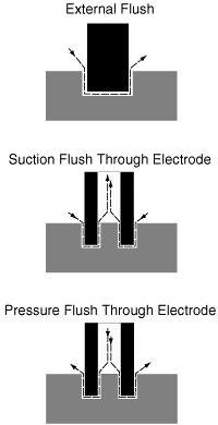
 Figure 1: The three types of flushing. |
|
 Figure 2: Metal-removal rates on copper and tool steel using the same operating parameters. |
|
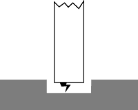
 Figure 3: Each individual spark creates a small crater in the workpiece finish. These craters combine to comprise the workpiece finish. |
|
Figure 1 depicts the three basic types of flushing—external, suction through the electrode, and pressure through the electrode. The choice of flushing method may be limited by the application. The shape and size of the electrode may prohibit through-the-electrode flushing.
Dissipated in the electrode. Energy dissipated in the electrode erodes it. Operating in positive polarity to the electrode when cutting copper results in more electrode wear than metal removal. Negative polarity to the electrode produces good metal removal and reduced electrode wear. Electrode wear can never be eliminated completely, but it can be minimized by operating at the optimum settings and having a good electrode/work-metal combination.
Dissipated in the workpiece. In the case of copper, energy is dissipated too quickly in the workpiece and interferes with efficient metal removal. Before the heat from the spark energy has a chance to create a molten pool of metal that can be ejected during the implosion of the gas bubble, the high thermal conductivity of the copper dissipates the energy throughout the workpiece and into the dielectric fluid. To overcome the effects of the copper’s thermal conductivity, the EDMer must use a higher amount of energy than he would to EDM even a difficult material such as tungsten carbide. EDMers who apply operating parameters that are successful on other metals to copper alloys will be disappointed with the results (Figure 2). They will see limited metal removal and excessive electrode wear.
Copper alloys also demand the use of negative polarity to the electrode along with a high amperage setting, if possible. Very small electrodes may not be able to handle a high amperage setting. The general guideline is 50-60 amps per square inch. Melting metal requires high amperage in the spark rather than a long on-time. Peak current, not length of on-time, seems to be the controlling factor for mrr and wear control.
EDMing copper and copper alloys is difficult, but efficient mrrs can be achieved without excessive electrode wear. Electrode wear cannot be eliminated, but it can be controlled by selecting the right material. Graphite electrodes ranging from ultrafine (<5µm) to superfine (10µm) classifications give good results when EDMing copper and copper alloys. Copper-impregnated graphites produce the best results, because they are the best conductors of the spark energy to the workpiece. Coarser graphites will suffer significantly more electrode wear.
Rough and Finish
For the rough-EDMing of copper and copper alloys, the best performance is achieved at a peak current of 35 to 55 amps. Lower amp settings will yield very low mrrs and result in extremely high electrode wear. Table 1 shows mrrs and the end wear percentage with the recommended electrode materials at 35 and 55 amps and the lowest recommended on-time. The optimum on-time range for 35-amp settings is 12 µsec. As the on-time increases, the wear increases, and the surface finish gets rougher. As Figure 3 shows, each spark creates a crater. The peaks and valleys of the overlapping craters produce the EDM finish. As the peak current and on-time increase, the craters become larger, producing a rougher finish and increasing the mrr.
At 55 amps, the on-time becomes less critical, because the EDMer will witness only small changes in mrr and slight variations in electrode wear by increasing on-time.
For finish-EDMing, surface finish can be improved with a lower peak current, but the mrr will, of course, suffer. Generally, short on-times combined with copper-impregnated graphites will provide the best finish. Table 2 shows surface finishes achieved in straight-plunge applications. Orbiting during the finishing operation will produce a better surface finish.
At 10 amps, the surface finish will be less than 200µin. Ra with all electrode materials, but copper-impregnated graphite electrodes will wear less. At 3.5 amps, the surface finish ranges from 55µin. Ra to 90µin. Ra, but the electrode wear is significantly higher than at the 10-amp settings unless a copper-impregnated graphite is used.
An EDMer can achieve predictable and consistent results on copper once he understands how to control the process and the importance of factors such as electrode material/copper combination, flushing, polarity, amperages, and on-times.
|
|||||||||||||||||||||||||||||||||
| Table 1: Metal-removal rates of various electrode grades on Ampcoloy using negative polarity. | |||||||||||||||||||||||||||||||||
|
|
|||||||||||||||||||||||||||||||||
|
|||||||||||||||||||||||||||||||||
| Table 2: Surface finish achieved by various electrode grades on Ampcoloy using negative polarity. | |||||||||||||||||||||||||||||||||
|
|
About the Author
Jimmy Sherman is senior applications engineer with Poco Graphite Inc., Decatur, TX.
Related Glossary Terms
- alloys
alloys
Substances having metallic properties and being composed of two or more chemical elements of which at least one is a metal.
- copper alloys
copper alloys
Copper containing specified quantities of alloying elements added to obtain the necessary mechanical and physical properties. The most common copper alloys are divided into six groups, and each group contains one of the following major alloying elements: brasses—major alloying element is zinc; phosphor bronzes—major alloying element is tin; aluminum bronzes—major alloying element is aluminum; silicon bronzes—major alloying element is silicon; copper-nickels and nickel-silvers—major alloying element is nickel; and dilute-copper or high-copper alloys, which contain small amounts of various elements such as beryllium, cadmium, chromium or iron.
- electrical-discharge machining ( EDM)
electrical-discharge machining ( EDM)
Process that vaporizes conductive materials by controlled application of pulsed electrical current that flows between a workpiece and electrode (tool) in a dielectric fluid. Permits machining shapes to tight accuracies without the internal stresses conventional machining often generates. Useful in diemaking.
- metal-removal rate
metal-removal rate
Rate at which metal is removed from an unfinished part, measured in cubic inches or cubic centimeters per minute.
- quenching
quenching
Rapid cooling of the workpiece with an air, gas, liquid or solid medium. When applicable, more specific terms should be used to identify the quenching medium, the process and the cooling rate.
- tungsten carbide ( WC)
tungsten carbide ( WC)
Intermetallic compound consisting of equal parts, by atomic weight, of tungsten and carbon. Sometimes tungsten carbide is used in reference to the cemented tungsten carbide material with cobalt added and/or with titanium carbide or tantalum carbide added. Thus, the tungsten carbide may be used to refer to pure tungsten carbide as well as co-bonded tungsten carbide, which may or may not contain added titanium carbide and/or tantalum carbide.
