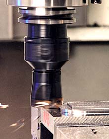
Machining dry eliminates the costs and hassles of using fluids.

Machining dry should be “standard operating procedure” for many metalcutting jobs. It’s not only possible to turn hardened materials dry, it’s profitable.
Just two decades ago, cutting fluids accounted for less than 3 percent of the cost of most machining processes. Fluids were so cheap that few machine shops gave them much thought. Times have changed, though.
Today, cutting fluids account for up to 15 percent of a shop’s production costs, and machine shop owners constantly worry about fluids.
Cutting fluids, especially those containing oil, have become a huge liability. Not only does the Environmental Protection Agency regulate the disposal of such mixtures, but many states and localities also have classified them as hazardous wastes and impose even stricter controls if they contain oil and certain alloys.
Because many high-speed machining operations and fluid nozzles create airborne mists, governmental bodies also limit the amount of cutting fluid mist allowed in the air. Moreover, the EPA has proposed even stricter standards for controlling such airborne particulate. And the Occupational Safety and Health Administration is considering an advisory committee’s recommendation to lower the permissible exposure limit to fluid mist.
The costs of maintenance, recordkeeping and compliance with current and proposed regulations is rapidly boosting the price of cutting fluids. Consequently, many machine shops are considering eliminating the costs and headaches associated with cutting fluids altogether by cutting dry.
Many shops that would like to cut dry, though, are unsure that they can. They believe that cutting fluids are necessary to reach higher speeds and to cut the harder materials that they must use to stay competitive. Many also believe that the cost of changing a wet operation to a dry one would be too high.
Neither is true. Machining dry should be “standard operating procedure” for many metalcutting jobs. It’s not only possible to turn hardened materials dry and mill dry at high speeds, it’s profitable. The trick is to know how to correctly integrate the tools, machines and cutting techniques.
‘Convention’ Behind Fluid Use
A major impediment to the growth of dry cutting is the conventional wisdom that metalworking fluids are necessary to attain acceptable finishes and long tool life. Although fluids are needed for many applications, research shows that this isn’t always the case with today’s cutting tool materials. Advanced grades of cemented carbide, especially those protected with a coating, cut more efficiently without cutting fluids when run at high speeds and temperatures. In fact, with interrupted cutting, the hotter the cutting zone, the more unsuitable a fluid is.
Consider a milling operation. Assuming that the fluid can overcome the centrifugal forces created by a milling cutter rotating at high speeds, the fluid vaporizes well before reaching the cutting zone, so it produces little or no cooling effect anyway. As a result, temperature fluctuations are greater when fluid is applied. A milling insert cools when it exits the cut. It heats up again when it re-enters the workpiece. Although the heating and cooling cycle occurs in dry machining, the temperature fluctuations are much greater when cutting fluid is present. The ensuing thermal shock can create stress in the insert and crack it prematurely.
A similar situation can arise during production turning. When cutting medium-carbon steel at speeds higher than 130 m/min., for example, uncoated carbide inserts engaged in the cut for less than 40 seconds can suffer pronounced thermal shock when exposed to coolant. This shock shortens tool life drastically by increasing crater wear slightly and flank wear significantly. Since the time in cut for most production turning is less than 40 seconds, cutting dry often extends tool life.
Drilling, however, is another matter. Cutting fluids are often necessary while drilling because they provide lubrication and flush chips from the hole. Without fluids, chips can bind in the hole, and the surface roughness average (Ra) can be twice as high as when drilling wet. Cutting fluids also can reduce the required machine torque by lubricating the point at which the drill margin touches the hole’s wall.
Although coated drills can duplicate the lubricating effect of fluids somewhat, the coatings that reduce cutting forces the most tend to offer the least abrasion-resistance.
The decision to cut wet or dry must be made on a case-by-case basis. A lubricious fluid often will prove beneficial in low-speed jobs, hard-to-machine materials, difficult applications and when surface-finish requirements are demanding. A fluid with a high cooling capacity can enhance performance in high-speed jobs, easy-to-machine materials, simple operations, and jobs prone to edge-buildup problems or having tight dimensional tolerances.
Many times, though, the extra performance capabilities that a cutting fluid offers is not worth the extra expense incurred. And in a growing number of applications, cutting fluids are simply unnecessary or downright detrimental. Modern cutting tools can run hotter than their predecessors and, sometimes, compressed air can be used to carry hot chips away from the cutting zone.
Coatings Manage Heat
In milling, cutting-zone temperatures fluctuate more when cutting fluid is used than when the operation is run dry. Large temperature fluctuations can create stress in the tool and crack it prematurely.
Coatings are a big part of the reason that cutting fluids are often unnecessary today. They control temperature fluctuations by inhibiting heat transfer from the cutting zone to the insert or tool. The coating acts as a heat barrier, because it has a much lower thermal conductivity than the tool substrate and the workpiece material. Coated inserts and tools, therefore, absorb less heat and can tolerate higher cutting temperatures, permitting the use of more aggressive cutting parameters in both turning and milling without sacrificing tool life.
Coating thickness is between 2 and 18 microns and plays an important role in a tool’s performance. Thinner coatings can better withstand the temperature fluctuations that arise during interrupted cuts than thicker coatings. The reason is because thinner coatings incur less stress, making them less likely to crack. During rapid cooling and heating, thick coatings experience what glass does when you heat or cool it too quickly. Running thinly coated inserts dry can extend tool life by up to 40 percent.
This is a big reason why the physical-vapor-deposition process typically is used to coat round tools and milling inserts. PVD coatings tend to be thinner than their chemical-vapor-deposition counterparts, and they adhere better to contours. In addition, PVD coatings can be deposited on carbide at much lower temperatures, so they find more use on the up-sharp edges and highly positive geometries of milling and turning tools.
Although titanium nitride is utilized for 80 percent of all coated tools, titanium aluminum nitride has emerged as the best PVD coating for cutting dry at high speeds. TiAlN can outperform TiN by as much as 4-to-1 in continuous, high-temperature cuts, such as those made during high-speed turning. TiAlN also excels in situations that involve high thermal stress, like dry milling and deep-hole drilling of small-diameter holes that cutting fluids have a difficult time penetrating.
TiAlN is harder than TiN at cutting temperatures and is the most thermally stable and chemically wear-resistant PVD coating available. Its hardness is as high as 3,500 Vickers, and its working temperature is as high as 1,470° F. Materials scientists suspect that these properties are attributable to an amorphous aluminum-oxide film that forms at the chip/tool interface when some of the aluminum at the coating surface oxidizes at high temperatures.
Research is under way to apply ultrathin, multilayer PVD coatings. Such deposition processes build a coating made of hundreds of layers that are only a few nanometers thick. In contrast, conventional PVD processes deposit several layers of micron-thick coatings.
Despite intense interest in PVD coatings, their CVD counterparts continue to be more popular for the machining of most ferrous materials. The higher deposition temperatures in CVD processes aid adhesion and allow higher cobalt concentrations in the substrate, which toughens the edges and helps the body resist deformation. Because CVD coatings tend to be thicker than PVD coatings, they require heavier hones on their cutting edge to prevent the coating from chipping—similar to how a thick layer of paint on the corner of a wall tends to chip. This design element also helps the tool resist abrasion wear and allows running at feeds up to 0.035 ipr.
CVD also is the only process that can deposit a usable layer of aluminum oxide, the most heat- and oxidation-resistant coating known. Aluminum oxide is a poor conductor that insulates the tool from the heat generated during chip formation. It forces heat to flow into the chip, making it an excellent CVD coating for most dry turning performed with carbide tools. It also protects the substrate at high cutting speeds and is the best coating for resisting both abrasive and crater wear.
Some Like It Dry
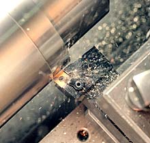
Developments in coating technology have spurred the growth of dry machining. Shown is Carboloy’s TX 150 turning grade, which combines a substrate designed for cast irons and a coating applied by the medium-temperature CVD process.
Although coated grades have better tool life and are more reliable in dry milling operations than in wet ones, the demand for faster cutting speeds is pushing cutting temperatures beyond the economical limits of carbide tools. Dry machining cast iron at 14,000 rpm and 1,575 ipm, for example, can heat the cutting zone in front of the tool to temperatures between 600° and 700° C. Metal-removal rates are similar to those seen while milling aluminum with more conventional techniques, but the temperature generated in cast iron is too high for conventional cutting tools.
As a consequence, the higher cutting speeds will require more wear-resistant cutting tool materials, ones that possess higher hot hardness. Cermet, cubic boron nitride and two ceramics—aluminum oxide and silicon nitride—fit the bill nicely. (Today, the term “ceramics” includes both aluminum oxide and silicon nitride, not just aluminum oxide as it did in the past.) Although not recommended for ferrous materials, polycrystalline diamond is another tool material that performs well in dry conditions. In all these materials, however, the tradeoff for their greater hot hardness and abrasion resistance is brittleness.
The advantages of each material are presented below.
-
Cermet: an advanced carbide. Cermet can run hotter than conventional carbide, but it lacks carbide’s shock resistance, toughness at medium-to-heavy loads, and strength at low cutting speeds and high feeds. Cermet has roughly the same edge strength as conventional carbide at small, constant loads; tends to withstand temperature and abrasion at high cutting speeds better; lasts longer; and imparts finer finishes. It also is better at resisting built-up edge and imparting good finishes when used on ductile and sticky materials.
The better hot hardness comes from the titanium compounds that make up the material. Cermet is a type of cemented carbide containing hard, titanium-based compounds (titanium carbide, titanium carbonitride and titanium nitride) in a nickel or nickel-molybdenum binder. Because of the metallic binder’s temperature limitation, cermet grades typically do not have a high enough hot hardness to machine materials above Rc 40.
Cermet also is more sensitive to fracture and feed-induced stress than coated and uncoated carbides. Therefore, it performs best in jobs requiring high accuracy and a fine finish. Ideal machining operations are those that don’t involve severe interruptions in the cut.
The feed limit for turning carbon steel is usually 0.025 ipr, and general-purpose milling can proceed at moderate feeds and high spindle speeds. If kept within these operating limits, cermet can retain a sharp cutting edge for a long time in high-volume jobs. Although cermet can pay for itself at conventional speeds and feeds simply by improving on the wear life and finish provided by a carbide tool, it also can boost productivity by cutting up to 20 percent faster in alloy steels and up to 50 percent faster in carbon steels, stainless steels and ductile irons.
- Ceramic: a family of materials. Ceramic cutting tools are similar to their cermet counterparts in that they are more chemically stable than carbide, last a long time and can machine at high cutting speeds. Pure aluminum oxide has extremely high thermal resistance but low strength and toughness, which means that it fractures easily if conditions are not optimal.
To make it less sensitive to cracking, cutting tool manufacturers add either zirconium oxide, to improve toughness, or a mixture of titanium carbide and titanium nitride, to boost shock resistance. Despite these additions, though, ceramic’s toughness is still much less than that of cemented carbide.
Another method for enhancing the toughness of aluminum oxide is to implant crystalline veins, or whiskers, of silicon carbide into the material. Although these whiskers typically average only 1 micron in diameter by 20 microns long, they are very strong and increase toughness, strength and thermal-shock resistance considerably. Whiskers can constitute up to 30 percent of the material.
Like aluminum oxide, silicon nitride has a higher hot hardness than carbide. It also withstands thermal and mechanical shocks better. Its main drawback compared to aluminum oxide is that its chemical stability isn’t as good when machining steel. However, silicon nitride machines gray cast iron at 1,450 sfm and higher.
Although the mrr can be high with a ceramic tool, the application must be right. For example, ceramic tools don’t work well in aluminum, but they excel in gray and nodular cast iron, hardened and some unhardened steels, and heat-resistant alloys. Even in these materials, though, success depends on the edge preparation, presentation of the tool to the work, the stability of the machine and setup, and utilizing the optimal machining parameters.
- CBN: hardness second to diamond. CBN is an extremely hard cutting tool material. It usually works best in materials harder than Rc 48. It has excellent hot hardness—up to 2,000° C. Although more brittle than carbide and less thermally and chemically stable than ceramic, it has higher impact strength and fracture resistance than ceramic tools. It also requires a less rigid machine to cut hardened metal. Moreover, properly tailored CBN tools can withstand the chip loads of high-power roughing, the pounding of interrupted cuts, and the heat and abrasion of fine finishing.
Proper tailoring for demanding jobs involves making sure that the machine and setup are rigid, edge preparations are large enough to prevent microscopic chipping and the tool substrate has a high CBN content. This allows the tool to operate at high speeds, with heavy mechanical edge loading and in severely interrupted cuts. These properties make such grades the tool material of choice for roughing hardened steel and pearlitic gray cast iron.
A tool with a low CBN content is more brittle, but it is better for hardened ferrous alloys. With a lower thermal conductivity and a higher compressive strength, CBN withstands the heat generated from high cutting speeds and negative rakes. Higher temperatures in the cutting zone soften the work material and aid chip separation. The negative geometry strengthens the tool, stabilizes the cutting edge, improves tool life and allows DOCs shallower than 0.010".
Because CBN tools can leave surface finishes finer than 16µin. and hold ±0.0005" accuracies when ganged, dry turning hardened workpieces is often an attractive alternative to messy, coolant-intensive grinding operations. CBN is a favorite tool material for hard turning and high-speed milling, but the ranges of applications for ceramic and CBN overlap tremendously, so cost-benefit analyses are typically necessary to determine which will offer the best results.
- PCD: excels in nonferrous work. As the hardest cutting tool material available, polycrystalline diamond is the best at withstanding abrasive wear. Its hardness and wear-resistance comes from the random crystal orientation and diamond-to-diamond bonding that inhibit crack propagation. Attaching PCD tips to cemented carbide inserts adds strength and shock resistance and can lengthen carbide tool life by up to 100 times.
Other properties, however, preclude its use for most machining operations. One is the affinity that PCD has for the iron in ferrous metals. The resulting chemical reaction limits this tool material to nonferrous applications. Another limiting property is its inability to withstand cutting-zone temperatures exceeding 600° C. Consequently, PCD cannot cut tough, high-tensile materials.
Nevertheless, PCD works well on nonferrous materials, particularly abrasive, high-silicon-content aluminum. Sharp cutting edges and highly positive rakes are essential to shear such materials efficiently and minimize cutting pressure and BUE.
Strengthen the Edge
Despite recent physical improvements and application developments, tools made from cermet, ceramics, CBN and PCD are still more brittle than carbide and cannot withstand as much stress. As a result, tools made from these materials must incorporate design features that add support and relieve stress.
It’s important, for example, to grind the cutting edge so that it redirects the cutting forces away from the insert’s edge and into its body. Three such edge preparations are appropriate: T-land, hone and honed T-land.
The T-land, a chamfer-like flat at the edge, replaces a weaker sharp point. The tool designer’s goal here is to find the minimum land width and angle that give the edge adequate strength and life; large widths and angles strengthen the insert but also increase cutting forces.
Hones are rounded-off sharp edges. Although they do not offer the same protection against chipping as T-lands, hones work well on advanced-material inserts used for finishing operations. These inserts must be run at shallow DOCs and low feed rates to keep cutting pressure to a minimum.
Hones also can strengthen T-lands when applied to the points at which the land intersects the rake and flank surfaces. When minute chipping occurs in applications such as the rough turning of steel with ceramics, hones can relieve stress at these points, strengthening the insert without having to make the land larger.
Besides specifying the best edge preparation for the job, the tool designer also must optimize the tool’s cutting geometry and ability to eject chips. Reducing cutting forces by widening the clearance angle puts less stress on the tool and lowers the temperature in the cutting zone. Rake angles that are as positive as possible also reduce cutting forces by creating a better shearing action, and wide-flute gullets aid chip evacuation by providing a large exit path, especially in drilling and threading.
Another way to keep tangential cutting forces low is to cut at high speeds. A high feed rate at very high spindle speeds reduces, rather than increases, the thrust against the workpiece by as much as 75 to 90 percent, depending on the tool and machining parameters. Moreover, milling cutters are more accurate than they were five years ago, and milling and turning machines have become more mechanically stable and rigid, thereby eliminating undue vibration. All of these developments support the use of brittle—but harder and more wear-resistant—cutting tool materials.
One of the benefits of using a tool that can withstand high temperatures is that chip formation can be extremely efficient. In cast iron, for example, the heat plasticizes the material in the cutting zone and lowers its yield strength. The result is a threefold increase in metal-removal efficiency, compared to conventional roughing. Because the feed rate is high, the tool shears the material so fast that most of the heat stays in the chip and does not have time to flow into the workpiece and distort it. Despite the higher cutting temperatures, the workpiece has more thermal stability and is more accurate than if it were cut at conventional removal rates.
Low-thrust finishing also minimizes static deformation of the workpiece, fixture and machine. Such an operation calls for utilizing low-density cutters with fewer inserts run at a low feed and high surface footage. Because less clamping forces are needed to hold the workpiece, fixtures can be simple. This gives the cutting tool greater access to a prismatic part.
Machine Considerations
When machining dry, it’s important to specify the right machine and outfit it correctly. Because speeds are typically faster, materials are often harder and cutting temperatures are much higher when machining dry, the machines must be rigid and powerful.
Before cutting dry on machining centers, users should strive to keep their tools short, make sure that their spindles are inherently rigid, and consider the machine’s speed and power ratings.
With respect to lathes cutting near-net shapes and hardened parts, tool turrets can work against the machines’ rigidity by creating a long path for resolving the cutting forces. A well-designed machine will resolve those forces along short, direct paths and will contain as few machine elements as possible to move and support the tool. After weighing accuracy against flexibility, you might consider bolting gang tools directly to the cross-slide to eliminate the rotary indexing mechanism.
Thermal stability is critical for accuracy, too. Some builders enhance the mechanics of their machining centers with software that compensates for thermal growth. Controlling temperature variation, however, should start with evacuating hot chips efficiently, thereby eliminating an important heat source inside the work envelope.
A well-designed machine doesn’t have pockets or plateaus where chips can accumulate. A good design incorporates augers and chip conveyors that move dry chips out of the machine without assistance from a cutting fluid. If chips become a problem, try using air instead of a fluid.
Telescoping covers, enclosures, seals and dust collectors are also required to protect the ballscrews, ways and operator from any dust that might become airborne. Although converting a machine designed for wet operations into a dry-cutting machine is possible, it’s usually cheaper and less problematic to buy one tailored for dry cutting. Its dust collector and compressed-air-delivery system are generally less expensive than the mist collector and coolant pump on a corresponding wet operation.
Operating costs are also lower with dry machining because it eliminates coolant management and disposal costs and because air compressors consume less electricity than coolant pumps.
All of these factors—along with relief from the myriad of existing cutting fluid regulations—heighten the appeal of “drying out” for those in the metalcutting industry.
About the Author
Don Graham is the manager of turning programs at Carboloy Inc., Warren, Mich.
Related Glossary Terms
- abrasive
abrasive
Substance used for grinding, honing, lapping, superfinishing and polishing. Examples include garnet, emery, corundum, silicon carbide, cubic boron nitride and diamond in various grit sizes.
- alloy steels
alloy steels
Steel containing specified quantities of alloying elements (other than carbon and the commonly accepted amounts of manganese, sulfur and phosphorus) added to cause changes in the metal’s mechanical and/or physical properties. Principal alloying elements are nickel, chromium, molybdenum and silicon. Some grades of alloy steels contain one or more of these elements: vanadium, boron, lead and copper.
- alloys
alloys
Substances having metallic properties and being composed of two or more chemical elements of which at least one is a metal.
- aluminum oxide
aluminum oxide
Aluminum oxide, also known as corundum, is used in grinding wheels. The chemical formula is Al2O3. Aluminum oxide is the base for ceramics, which are used in cutting tools for high-speed machining with light chip removal. Aluminum oxide is widely used as coating material applied to carbide substrates by chemical vapor deposition. Coated carbide inserts with Al2O3 layers withstand high cutting speeds, as well as abrasive and crater wear.
- amorphous
amorphous
Not having a crystal structure; noncrystalline.
- built-up edge ( BUE)
built-up edge ( BUE)
1. Permanently damaging a metal by heating to cause either incipient melting or intergranular oxidation. 2. In grinding, getting the workpiece hot enough to cause discoloration or to change the microstructure by tempering or hardening.
- built-up edge ( BUE)2
built-up edge ( BUE)
1. Permanently damaging a metal by heating to cause either incipient melting or intergranular oxidation. 2. In grinding, getting the workpiece hot enough to cause discoloration or to change the microstructure by tempering or hardening.
- carbon steels
carbon steels
Known as unalloyed steels and plain carbon steels. Contains, in addition to iron and carbon, manganese, phosphorus and sulfur. Characterized as low carbon, medium carbon, high carbon and free machining.
- cast irons
cast irons
Cast ferrous alloys containing carbon in excess of solubility in austenite that exists in the alloy at the eutectic temperature. Cast irons include gray cast iron, white cast iron, malleable cast iron and ductile, or nodular, cast iron. The word “cast” is often left out.
- centers
centers
Cone-shaped pins that support a workpiece by one or two ends during machining. The centers fit into holes drilled in the workpiece ends. Centers that turn with the workpiece are called “live” centers; those that do not are called “dead” centers.
- ceramics
ceramics
Cutting tool materials based on aluminum oxide and silicon nitride. Ceramic tools can withstand higher cutting speeds than cemented carbide tools when machining hardened steels, cast irons and high-temperature alloys.
- chemical vapor deposition ( CVD)
chemical vapor deposition ( CVD)
High-temperature (1,000° C or higher), atmosphere-controlled process in which a chemical reaction is induced for the purpose of depositing a coating 2µm to 12µm thick on a tool’s surface. See coated tools; PVD, physical vapor deposition.
- clearance
clearance
Space provided behind a tool’s land or relief to prevent rubbing and subsequent premature deterioration of the tool. See land; relief.
- coated tools
coated tools
Carbide and high-speed-steel tools coated with thin layers of aluminum oxide, titanium carbide, titanium nitride, hafnium nitride or other compounds. Coating improves a tool’s resistance to wear, allows higher machining speeds and imparts better finishes. See CVD, chemical vapor deposition; PVD, physical vapor deposition.
- coolant
coolant
Fluid that reduces temperature buildup at the tool/workpiece interface during machining. Normally takes the form of a liquid such as soluble or chemical mixtures (semisynthetic, synthetic) but can be pressurized air or other gas. Because of water’s ability to absorb great quantities of heat, it is widely used as a coolant and vehicle for various cutting compounds, with the water-to-compound ratio varying with the machining task. See cutting fluid; semisynthetic cutting fluid; soluble-oil cutting fluid; synthetic cutting fluid.
- cubic boron nitride ( CBN)
cubic boron nitride ( CBN)
Crystal manufactured from boron nitride under high pressure and temperature. Used to cut hard-to-machine ferrous and nickel-base materials up to 70 HRC. Second hardest material after diamond. See superabrasive tools.
- cubic boron nitride ( CBN)2
cubic boron nitride ( CBN)
Crystal manufactured from boron nitride under high pressure and temperature. Used to cut hard-to-machine ferrous and nickel-base materials up to 70 HRC. Second hardest material after diamond. See superabrasive tools.
- cutting fluid
cutting fluid
Liquid used to improve workpiece machinability, enhance tool life, flush out chips and machining debris, and cool the workpiece and tool. Three basic types are: straight oils; soluble oils, which emulsify in water; and synthetic fluids, which are water-based chemical solutions having no oil. See coolant; semisynthetic cutting fluid; soluble-oil cutting fluid; synthetic cutting fluid.
- cutting tool materials
cutting tool materials
Cutting tool materials include cemented carbides, ceramics, cermets, polycrystalline diamond, polycrystalline cubic boron nitride, some grades of tool steels and high-speed steels. See HSS, high-speed steels; PCBN, polycrystalline cubic boron nitride; PCD, polycrystalline diamond.
- edge preparation
edge preparation
Conditioning of the cutting edge, such as a honing or chamfering, to make it stronger and less susceptible to chipping. A chamfer is a bevel on the tool’s cutting edge; the angle is measured from the cutting face downward and generally varies from 25° to 45°. Honing is the process of rounding or blunting the cutting edge with abrasives, either manually or mechanically.
- feed
feed
Rate of change of position of the tool as a whole, relative to the workpiece while cutting.
- fixture
fixture
Device, often made in-house, that holds a specific workpiece. See jig; modular fixturing.
- flank wear
flank wear
Reduction in clearance on the tool’s flank caused by contact with the workpiece. Ultimately causes tool failure.
- flat ( screw flat)
flat ( screw flat)
Flat surface machined into the shank of a cutting tool for enhanced holding of the tool.
- gang cutting ( milling)
gang cutting ( milling)
Machining with several cutters mounted on a single arbor, generally for simultaneous cutting.
- grinding
grinding
Machining operation in which material is removed from the workpiece by a powered abrasive wheel, stone, belt, paste, sheet, compound, slurry, etc. Takes various forms: surface grinding (creates flat and/or squared surfaces); cylindrical grinding (for external cylindrical and tapered shapes, fillets, undercuts, etc.); centerless grinding; chamfering; thread and form grinding; tool and cutter grinding; offhand grinding; lapping and polishing (grinding with extremely fine grits to create ultrasmooth surfaces); honing; and disc grinding.
- hard turning
hard turning
Single-point cutting of a workpiece that has a hardness value higher than 45 HRC.
- hardness
hardness
Hardness is a measure of the resistance of a material to surface indentation or abrasion. There is no absolute scale for hardness. In order to express hardness quantitatively, each type of test has its own scale, which defines hardness. Indentation hardness obtained through static methods is measured by Brinell, Rockwell, Vickers and Knoop tests. Hardness without indentation is measured by a dynamic method, known as the Scleroscope test.
- inches per minute ( ipm)
inches per minute ( ipm)
Value that refers to how far the workpiece or cutter advances linearly in 1 minute, defined as: ipm = ipt 5 number of effective teeth 5 rpm. Also known as the table feed or machine feed.
- land
land
Part of the tool body that remains after the flutes are cut.
- metalcutting ( material cutting)
metalcutting ( material cutting)
Any machining process used to part metal or other material or give a workpiece a new configuration. Conventionally applies to machining operations in which a cutting tool mechanically removes material in the form of chips; applies to any process in which metal or material is removed to create new shapes. See metalforming.
- metalworking
metalworking
Any manufacturing process in which metal is processed or machined such that the workpiece is given a new shape. Broadly defined, the term includes processes such as design and layout, heat-treating, material handling and inspection.
- micron
micron
Measure of length that is equal to one-millionth of a meter.
- milling
milling
Machining operation in which metal or other material is removed by applying power to a rotating cutter. In vertical milling, the cutting tool is mounted vertically on the spindle. In horizontal milling, the cutting tool is mounted horizontally, either directly on the spindle or on an arbor. Horizontal milling is further broken down into conventional milling, where the cutter rotates opposite the direction of feed, or “up” into the workpiece; and climb milling, where the cutter rotates in the direction of feed, or “down” into the workpiece. Milling operations include plane or surface milling, endmilling, facemilling, angle milling, form milling and profiling.
- milling cutter
milling cutter
Loosely, any milling tool. Horizontal cutters take the form of plain milling cutters, plain spiral-tooth cutters, helical cutters, side-milling cutters, staggered-tooth side-milling cutters, facemilling cutters, angular cutters, double-angle cutters, convex and concave form-milling cutters, straddle-sprocket cutters, spur-gear cutters, corner-rounding cutters and slitting saws. Vertical cutters use shank-mounted cutting tools, including endmills, T-slot cutters, Woodruff keyseat cutters and dovetail cutters; these may also be used on horizontal mills. See milling.
- milling machine ( mill)
milling machine ( mill)
Runs endmills and arbor-mounted milling cutters. Features include a head with a spindle that drives the cutters; a column, knee and table that provide motion in the three Cartesian axes; and a base that supports the components and houses the cutting-fluid pump and reservoir. The work is mounted on the table and fed into the rotating cutter or endmill to accomplish the milling steps; vertical milling machines also feed endmills into the work by means of a spindle-mounted quill. Models range from small manual machines to big bed-type and duplex mills. All take one of three basic forms: vertical, horizontal or convertible horizontal/vertical. Vertical machines may be knee-type (the table is mounted on a knee that can be elevated) or bed-type (the table is securely supported and only moves horizontally). In general, horizontal machines are bigger and more powerful, while vertical machines are lighter but more versatile and easier to set up and operate.
- physical vapor deposition ( PVD)
physical vapor deposition ( PVD)
Tool-coating process performed at low temperature (500° C), compared to chemical vapor deposition (1,000° C). Employs electric field to generate necessary heat for depositing coating on a tool’s surface. See CVD, chemical vapor deposition.
- polycrystalline diamond ( PCD)
polycrystalline diamond ( PCD)
Cutting tool material consisting of natural or synthetic diamond crystals bonded together under high pressure at elevated temperatures. PCD is available as a tip brazed to a carbide insert carrier. Used for machining nonferrous alloys and nonmetallic materials at high cutting speeds.
- polycrystalline diamond ( PCD)2
polycrystalline diamond ( PCD)
Cutting tool material consisting of natural or synthetic diamond crystals bonded together under high pressure at elevated temperatures. PCD is available as a tip brazed to a carbide insert carrier. Used for machining nonferrous alloys and nonmetallic materials at high cutting speeds.
- rake
rake
Angle of inclination between the face of the cutting tool and the workpiece. If the face of the tool lies in a plane through the axis of the workpiece, the tool is said to have a neutral, or zero, rake. If the inclination of the tool face makes the cutting edge more acute than when the rake angle is zero, the rake is positive. If the inclination of the tool face makes the cutting edge less acute or more blunt than when the rake angle is zero, the rake is negative.
- relief
relief
Space provided behind the cutting edges to prevent rubbing. Sometimes called primary relief. Secondary relief provides additional space behind primary relief. Relief on end teeth is axial relief; relief on side teeth is peripheral relief.
- stainless steels
stainless steels
Stainless steels possess high strength, heat resistance, excellent workability and erosion resistance. Four general classes have been developed to cover a range of mechanical and physical properties for particular applications. The four classes are: the austenitic types of the chromium-nickel-manganese 200 series and the chromium-nickel 300 series; the martensitic types of the chromium, hardenable 400 series; the chromium, nonhardenable 400-series ferritic types; and the precipitation-hardening type of chromium-nickel alloys with additional elements that are hardenable by solution treating and aging.
- threading
threading
Process of both external (e.g., thread milling) and internal (e.g., tapping, thread milling) cutting, turning and rolling of threads into particular material. Standardized specifications are available to determine the desired results of the threading process. Numerous thread-series designations are written for specific applications. Threading often is performed on a lathe. Specifications such as thread height are critical in determining the strength of the threads. The material used is taken into consideration in determining the expected results of any particular application for that threaded piece. In external threading, a calculated depth is required as well as a particular angle to the cut. To perform internal threading, the exact diameter to bore the hole is critical before threading. The threads are distinguished from one another by the amount of tolerance and/or allowance that is specified. See turning.
- titanium aluminum nitride ( TiAlN)
titanium aluminum nitride ( TiAlN)
Often used as a tool coating. AlTiN indicates the aluminum content is greater than the titanium. See coated tools.
- titanium aluminum nitride ( TiAlN)2
titanium aluminum nitride ( TiAlN)
Often used as a tool coating. AlTiN indicates the aluminum content is greater than the titanium. See coated tools.
- titanium carbide ( TiC)
titanium carbide ( TiC)
Extremely hard material added to tungsten carbide to reduce cratering and built-up edge. Also used as a tool coating. See coated tools.
- titanium carbonitride ( TiCN)
titanium carbonitride ( TiCN)
Often used as a tool coating. See coated tools.
- titanium nitride ( TiN)
titanium nitride ( TiN)
Added to titanium-carbide tooling to permit machining of hard metals at high speeds. Also used as a tool coating. See coated tools.
- titanium nitride ( TiN)2
titanium nitride ( TiN)
Added to titanium-carbide tooling to permit machining of hard metals at high speeds. Also used as a tool coating. See coated tools.
- turning
turning
Workpiece is held in a chuck, mounted on a face plate or secured between centers and rotated while a cutting tool, normally a single-point tool, is fed into it along its periphery or across its end or face. Takes the form of straight turning (cutting along the periphery of the workpiece); taper turning (creating a taper); step turning (turning different-size diameters on the same work); chamfering (beveling an edge or shoulder); facing (cutting on an end); turning threads (usually external but can be internal); roughing (high-volume metal removal); and finishing (final light cuts). Performed on lathes, turning centers, chucking machines, automatic screw machines and similar machines.
- work envelope
work envelope
Cube, sphere, cylinder or other physical space within which the cutting tool is capable of reaching.
- yield strength
yield strength
Stress at which a material exhibits a specified deviation from proportionality of stress and strain. An offset of 0.2 percent is used for many metals. Compare with tensile strength.