Driving diesel developments: Drilling Performance
Machining large compacted graphite iron castings for diesel engine components is challenging, but applying the proper tools and techniques can help.
Machining large compacted graphite iron castings for diesel engine components is challenging, but applying the proper tools and techniques can help.
Regardless of the fluctuations in the price of diesel fuel, the usage trend is upward while emission requirements head south. To remain competitive, producers of diesel components—especially engine blocks and cylinder heads—must provide parts that are lighter to reduce fuel consumption while providing the required performance characteristics. While aluminum engine blocks enable “lightweighting” compared to gray cast iron ones and continue to gain market share, iron is still needed for large-truck engines and high-torque engines in lighter vehicles.
“Those engines get pretty hot and there’s more concern about the engine failing so they use iron,” said Dick Schultz, project consultant for Ducker Worldwide, Troy, Mich., adding that up to 72 percent of engine blocks are aluminum now and that share will probably rise to 95 percent by 2015.
To lightweight those components that still need to be made of iron, part manufacturers are switching from gray cast iron to compacted graphite iron, which is a stronger material because it has about a 70 percent higher tensile strength and 45 percent greater stiffness and therefore can be used to make a lighter engine block with improved performance. “Manufacturers can thin the walls and webs so they end up with a CGI block that is lighter than the original aluminum block,” said Stan Weidmer, process development engineer for machine tool builder Makino Inc., Mason, Ohio. “That’s just mind-blowing.”
When an auto part must be made of iron, gray iron has a cost advantage vs. CGI because the latter is a highly engineered material. That means CGI is more difficult to produce at the foundry than gray iron, requiring tighter control of the alloying elements. Those include manganese, magnesium, chromium and titanium. For example, a foundry must hold magnesium content to a 0.003 percent tolerance.
“At the foundries, it’s tricky to get a very specific cocktail or recipe for CGI,” Weidmer said. “They stumbled on it by accident, but then it was difficult to repeat.” That occurred in the mid-’70s as a result of an off-spec melt of ductile iron. It’s often said CGI is a special form of ductile iron—an especially bad one. “If you were to lay these three irons side by side, you’d have gray on the left, ductile in the middle and CGI, which is the most difficult to machine, on the right,” Weidmer said.
Weidmer added, however, that various CGI grades exist. “There is not one standard CGI,” he said. “The real trick is figuring out exactly what’s in it and then customizing your speeds, feeds and DOCs based around that particular material.”
Slow Down, Live Less
One element CGI doesn’t include is sulfur because, with it, the desired graphite shape could not be achieved. The graphite shape in CGI is vermicular, or wormlike. In contrast, gray iron has a flaky graphite structure that’s relatively easy to machine and ductile iron’s graphite structure is nodular, or spheroid- al, and those nodules are surrounded by an abrasive silicon-carbide shell. According to Makino, in the case of gray iron, sulfur combines with the manganese in the iron and deposits itself on an insert, enabling carbide tools to be run at two to three times normal cutting speeds and PCBN to machine at advanced speeds because of this coating.

Courtesy of Sandvik Coromant
Sandvik Coromant reports that its K20W-grade insert with CGI-optimized KX positive geometries imparts a fine finish and minimizes burrs. formation.
Without the sulfur, auto part manufacturers experience a significant reduction in tool life and cutting speeds when cutting CGI. When milling CGI, for example, tool life is 40 to 50 percent shorter compared to milling gray iron, according to Jose R. Gamarra, engineering manager for Sandvik do (São Paulo) Brasil S.A. He added that the toolmaker recommends reducing the cutting speed by 40 percent for CGI vs. gray iron. “For example, in a milling operation for gray cast iron, normally we recommend 150 to 200 meters per minute,” Gamarra said. “We recommend 100 to 120 meters per minute for CGI.” He added that the recommended starting-point feed for CGI is 0.1 to 0.12 mm per tooth and the DOC is 3mm to 5mm.
Unlike milling, which is an interrupted operation where inserts move in and out of the cut as a tool rotates, uninterrupted operations, such as boring, turning and drilling, pose a greater challenge when machining CGI. “Because of this long contact of the inserts with the material, CGI destroys the inserts,” Gamarra said. “When cylinder boring, you can consider around 70 percent less tool life.”
Johannes Schneider, product management and marketing leader for SPK Cutting Tool Div. of CeramTec AG, Plochingen, Germany, concurred that machining CGI leads to more rapid cutting edge wear compared to gray iron because of the workpiece material’s structure and composition—especially for uninterrupted operations. Setting the baseline speed and feed at 100 percent when milling gray iron, he indicated that the speed is 100 to 120 percent and the feed is 80 to 100 percent when cutting CGI with ceramic tools, and the speed is 60 percent and the feed is 100 percent when cutting CGI with tungsten-carbide tools. When boring and turning, the speed is 30 percent and the feed is 90 to 110 percent when cutting CGI with ceramic and tungsten-carbide tools.
Schneider added that to effectively mill CGI, tungsten-carbide tools must be coated and ceramic ones can be coated or uncoated, such as the alumina-coated SL858C-grade SiAlON ceramic or the uncoated SL808-grade SiAlON ceramic. For uninterrupted turning and boring operations, he recommends coatings for all carbide and ceramic tools, such as the coated SL658C-grade SiAlON ceramic.
Appropriate coatings include PVD aluminum titanium nitride and titanium nitride, Gamarra noted. He added that PCBN is another suitable cutting tool material for machining CGI, especially when finishing, and tooling a milling cutter with ceramic and PCBN wiper inserts can extend tool life while imparting a fine surface finish. That might involve using 24 ceramic and two PCBN inserts in a 250mm-dia. milling cutter. “Normally, the surface finish is from 1 to 2 μm Ra,” Gamarra said.
For machining CGI with carbide, Sandvik Coromant Co., Fair Lawn, N.J., says it developed the K20D- and K20W-grade inserts with CGI-optimized KX positive geometries. The K20D is for dry machining and the K20W is for wet machining. “The tendency is for people to machine CGI dry,” Gammara said, “but the producers of cylinder blocks prefer to machine those products using coolant because of the dust.”
In addition to controlling the tiny, graphite-containing, dustlike chips, flood coolant reduces the cutting temperature, according to Schneider. In addition, he recommends applying coolant to extend tool life, primarily when turning or boring CGI.
Even with a well-planned machining environment, cutting CGI still presents obstacles. “The problem with CGI is you can’t use some of the higher-end inserts, the CBNs or the special coatings designed to run at faster surface footages in standard gray cast iron,” Weidmer said. “CGI is really in a category unto its own. As a result, you have to slow everything way down, which increases cycle time, and even then it eats inserts.”
Weidmer noted that PCBN and coated carbide tools are not effective at cutting CGI because machining it with those tools produces long chips, which transfers more heat to the insert and thereby accelerates wear.
Doing it Helically
Rather than having inserts continually engaged and experiencing constant heating when boring and drilling, Weidmer recommends turning an uninterrupted cut into an interrupted one with helical interpolation, which provides two positive changes: multiple inserts share the load rather than one insert doing all the work and a heating and cooling cycle is provided for each insert. “Now you have an insert that goes into the cut, gets a little hot but then comes out of the cut and has 180° of rotation to cool down and get set up for the next cut,” he said. “We see substantially more stability and insert life by taking conventional noninterrupted cutting paths and interrupting them.”
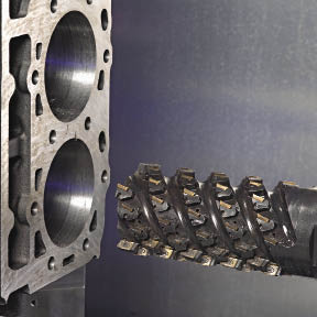
Courtesy of Makino
A prototype long-edge plunge milling cutter from Sandvik Coromant circular interpolates a cylinder bore in a CGI engine block.
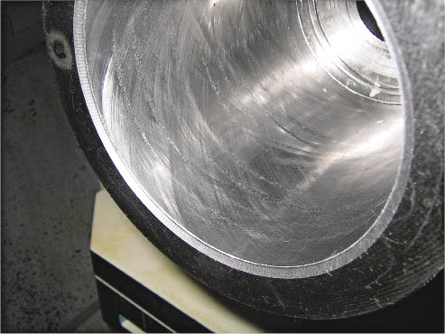
Courtesy of Makino
A honed CGI test cylinder illustrates the surface finish that can be achieved without handwork.
Table 1: Comparison of material properties.
| Gray iron (Class 30) | Compacted graphite iron (Grade 300) | Ductile iron (Grade 65-45-12) | |
|
Minimum tensile strength, KSI (MPa) |
30 (207) |
43.5 (300) |
65 (448) |
|
Minimum yield strength, KSI (MPa) |
— |
30.5 (210) Finish task to continue reading
Review the print ads from this magazine to continueThis quick advertiser review unlocks the rest of the article and keeps the full-screen reader focused on the ads instead of the page chrome. Task complete
Continue readingThanks for supporting the advertisers that help keep the magazine moving. Continue reading below.
September 2009
September 2009 |


MFGAxis Discussion