To minimize the effects of stream deflection in A WJ, the stream’s traverse speed must be carefully regulated. Today, this can be done automatically.
Abrasive waterjet (AWJ) machines are based on a promising concept. A powerful pump shoots a stream of water carrying an abrasive medium through a tiny opening in a nozzle. The stream, which has a pressure and a velocity high enough to pierce metal, produces a cut approximately 0.030" wide. By moving its nozzle along a prescribed path, an AWJ machine guides this stream to cut parts out of sheets of material up to 2" thick. Under ideal conditions, the machine can create sharp external corners, and it can create internal corners with radii as tight as 0.015", which is equal to the stream’s radius.
There are other benefits of cutting hard materials this way. For one, the process requires no tool changes, so setups take very little time. For another, cutting forces are low, so only minimal fixturing is needed. AWJ’s developers thought these benefits would make a high-pressure stream of water the perfect cutting tool for single parts and short runs, and they expected manufacturers to eagerly embrace the new technology. They were almost right.
Users may have been attracted to AWJ initially because of its benefits, but they soon discovered that AWJ machining was a complex process that required more programming sophistication than most small and medium-size shops possessed. Generally, it was only the larger manufacturers that found a use for the technology. As a result, AWJ machining was seldom chosen to supplement - let alone displace - conventional machining.
However, there is new motion-control technology on the market that may convince users to give AWJ another chance. This technology simplifies the control of the machine by anticipating the stream’s behavior at each point along the tool path and automatically compensating for changes in the stream that occur as it follows this path.
Manual Control
On most AWJ machines, an operator has to perform these calculations and machine adjustments himself. This is not a simple task. Every AWJ application is affected to some extent by the deflection of the waterjet stream as it moves across the workpiece (Figure 1). The faster the stream moves, the more it is bent. A stream following the tool path at high speed cuts the material the way a wheel cutter might cut, with the stream exiting the bottom of the part a distance (L on Figure 1) behind the point the stream enters the part. On straight cuts, the stream can be moved swiftly across the workpiece, because the stream’s deflection does not affect accuracy. But on corners, where stream deflection can cause cutting errors, the traverse speed of the stream must be reduced. To cut complex shapes with a variety of corners and curves, the traverse speed of the machine must be constantly adjusted. This ensures that at all times the stream is moving fast enough to maintain productivity, but never so fast that accuracy is compromised.
Figure 1:As the abrasivejet stream traverses the part, the stream is deflected. Distance L represents the degree of deflection, which is a function of traverse speed.
To choose appropriate speeds manually, an operator must assess the impact of seven different process parameters in addition to traverse speed that affect the stream’s behavior. Typically, these parameters are set at the beginning of the operation, and they do not vary while the machine is cutting the part. The parameters include the material being cut, the type of abrasive used, the pressure driving the jet, the jet orifice diameter, the abrasive flow rate, the diameter of the tube in which the water and abrasive mix, and the material thickness. Machine-based limitations must also be considered. These include the machine’s top speed, its acceleration rate, and the amount of jerk the machine can handle without excessive vibration.
For help, the operator may consult a table or a mathematical model that will give him speed data for cutting a straight line in a given material of a certain thickness. To use this information, however, the operator has to modify the speed recommendations to take into account the effects that factors other than material and thickness have on the behavior of the waterjet stream. By trial and error, the operator calculates where and to what extent it will be necessary to vary the recommended speed to maintain accuracy as the stream follows the tool path. For these calculations, he uses models of stream behavior that tell him how much the stream will deflect at a given speed.
If these calculations are being performed for one-off or prototype parts, the operator may choose an average speed to begin the cutting process. Then, using the machine’s feed-rate override control, he will adjust the speed according to his past experience as the machine is cutting the part. It takes a high degree of skill to accurately adjust the machine’s speed on the fly, and even a skilled operator will have difficulty achieving repeatable precision from part to part.
For a long run of parts, the operator can use the results of his trial-and-error tests to code the necessary speed changes into the part program. The program as it is originally written probably won’t be able to produce good parts, because it is extremely difficult to set speeds correctly as a function of part geometry. The operator will have to perform a series of trial runs to tweak the speed settings until the program is producing acceptable parts.
An operator trying to program speeds into a typical AWJ machine controller will find himself handicapped by the controller’s limitations. Most of these controllers are high-priced specialty computers designed to translate cutting-path specifications into incremental commands in real time. Such a controller is capable of following the velocity profiles prescribed by its manufacturer, but these profiles only provide constant speeds with prescribed acceleration between speeds. The operator can’t use these profiles to control traverse speed along every section of a complex curve, because the controller can’t be commanded in this way. Typically, the operator can choose a top speed and an acceleration for each element of the tool path, but the controller won’t allow him to vary the speed along an element.
Most PC-based AWJ controllers also lack the ability to cut complex shapes accurately. These controllers use PCs with special plug-in cards installed in the computers’ expansion slots. The cards can take the place of more expensive machine tool controllers - they can perform all the necessary calculations and send a stream of instructions to the machine to control tool motion - but they have the same limitations as conventional machine tool controllers.
Compute First, Move Later
A "compute first, move later" motion-control algorithm that stores instructions in fine detail was not economically feasible. But because fast, memory-laden computers have become so accessible, AWJ developers have been able to introduce a new type of controller that harnesses the computer’s power to evaluate the interaction between the waterjet stream and the material, calculating the optimum cutting speed for any point along the tool path (Figure 2). By calculating speeds and tool movements for the entire tool path before any material is cut, the system has the resources and time to consider the complex interplay of several factors as it chooses optimum traverse speeds.
The system also uses the additional speed and memory capacity of modern PCs to calculate traverse speeds for much smaller increments of the tool path than older controllers can. This newer technology calculates and stores the speeds for an entire tool path in increments as small as 2000 points per inch. Once the tool path has been generated, it can be displayed along with the estimated cutting time before cutting actually begins. At a command from the operator, the instructions are then sent in a timed sequence to the machine to actually cut the part.
The system is driven by software running on a standard DOS-compatible PC. Early systems used 66-Mhz 486 computers. Current machines have been updated with faster Pentium processors. About 8MB of random-access memory is required for the system. If more memory is available, it will allow the system to compute cutting programs with longer tool paths. Unlike older PC-based controllers, this system can talk to the AWJ machine without a special plug-in card or other hardware. Instead, the computer and the machine are linked through the computer’s parallel port. This simple connection makes it possible for the user to upgrade the system with a faster computer if necessary.
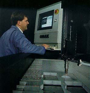
Figure 2: This recently introduced AWJ system uses a motion-control system that automatically calculates tool paths and speeds.
Because of the system’s easy-to-understand interface and automated functions, even an operator with little specialized training or experience can make successful and accurate cuts using AWJ. To cut a part using the software, the operator enters data about the material and its thickness through a graphical interface. Data describing other process variables are passed to the system through a setup file that the operator can modify when necessary. The operator can enter part dimensions and geometry with a drawing program that is part of the system package. The software also can import CAD files that are in data-exchange format.
As the operator is entering part information, he can also assign a quality level to each segment of the part drawing. This quality setting guides the system in its choice of traverse speeds for that section. Higher quality settings prompt the system to choose slower speeds. To calculate the optimal tool-path and machine settings, the system automatically feeds all of this information into an empirical mathematical model of the cutting process that was created using data gathered from a series of cutting tests. This model can predict the behavior of the stream in a wide range of materials, taking into account the effects of process variables and machine limitations.
An operator can achieve extremely accurate results when a PC running this software is used to control a high-performance AWJ machine. This combination of controller and hardware can be found in integrated systems now on the market. Such a system, which includes a PC to run the controller, sends up to 6,000 speed and motion instructions per second to a machine equipped with an ultra-high-pressure pump, an AWJ delivery system, and a precise 2-axis machining table. Shops use the system to cut complex parts out of metal, plastic, glass, composites, and ceramics to a dimensional tolerance of ±0.005". The system can contour flat materials up to 2" thick directly from a 2-D CAD or vector-based drawing system. An expert system that can analyze the part and generate the most efficient tool path is also part of the software. With all of this power so readily available, operators can go from drawing to finished part very quickly.
About the Author
John Olsen is general manager of Omax Corp., Auburn, WA.
Related Glossary Terms
- 2-D
2-D
Way of displaying real-world objects on a flat surface, showing only height and width. This system uses only the X and Y axes.
- abrasive
abrasive
Substance used for grinding, honing, lapping, superfinishing and polishing. Examples include garnet, emery, corundum, silicon carbide, cubic boron nitride and diamond in various grit sizes.
- abrasive waterjet ( AWJ)
abrasive waterjet ( AWJ)
System that uses high-pressure waterjets in combination with a slurry of fine abrasive grains to machine materials. See waterjet cutting.
- abrasive waterjet ( AWJ)2
abrasive waterjet ( AWJ)
System that uses high-pressure waterjets in combination with a slurry of fine abrasive grains to machine materials. See waterjet cutting.
- ceramics
ceramics
Cutting tool materials based on aluminum oxide and silicon nitride. Ceramic tools can withstand higher cutting speeds than cemented carbide tools when machining hardened steels, cast irons and high-temperature alloys.
- composites
composites
Materials composed of different elements, with one element normally embedded in another, held together by a compatible binder.
- computer-aided design ( CAD)
computer-aided design ( CAD)
Product-design functions performed with the help of computers and special software.
- cutting speed
cutting speed
Tangential velocity on the surface of the tool or workpiece at the cutting interface. The formula for cutting speed (sfm) is tool diameter 5 0.26 5 spindle speed (rpm). The formula for feed per tooth (fpt) is table feed (ipm)/number of flutes/spindle speed (rpm). The formula for spindle speed (rpm) is cutting speed (sfm) 5 3.82/tool diameter. The formula for table feed (ipm) is feed per tooth (ftp) 5 number of tool flutes 5 spindle speed (rpm).
- flat ( screw flat)
flat ( screw flat)
Flat surface machined into the shank of a cutting tool for enhanced holding of the tool.
- parallel
parallel
Strip or block of precision-ground stock used to elevate a workpiece, while keeping it parallel to the worktable, to prevent cutter/table contact.
- tolerance
tolerance
Minimum and maximum amount a workpiece dimension is allowed to vary from a set standard and still be acceptable.