It’s often a good idea to slow down when cutting metal. That’s not a popular notion today. A lot of manufacturing engineers consider any approach that doesn’t push cutting tools to their limits as being overly conservative.
But pushing tools too hard can lead to catastrophic failure. Moderation leads to process consistency, which should be important to every machine shop.
Use Common Sense
If you consistently run a tool near the high end of the manufacturer’s parameters, that’s good. But if you find success near the low end, or even lower, you’re not a failure. Cutting two minutes from a 10-minute process is significant. But the same two minutes trimmed from a one-hour process isn’t much.
Ask yourself hard questions about a specific application before altering it. If, for instance, you have a part that has a long boring cycle and a comparatively short drilling cycle, would it be cost-effective to push hard to reduce the drilling time? Or, given that only 20 percent of the average machining cycle is devoted to cutting, would it make sense to try to reduce the drilling time by 30 percent if you only decrease total cycle time by 6 percent?
Then there’s the technology question. Should you buy the newest tool or tool-related system? Through-coolant tooling comes to mind. People rave that these systems significantly reduce cycle times because they allow tools to run faster. But the tooling isn’t cheap, and why bother to purchase a system if your processes don’t demand it?
Our shop uses simple flood coolant to drill cast iron every day at 25 to 30 ipm and to depths of 2.5 to 3.0 diameters. Solid-carbide drills with three flutes have proved very successful for us. We run them at about 70 percent of the manufacturer-recommended surface speed.
-
We do this because drilling 25 holes 1" deep at 25 ipm equals one minute of cutting time. So, if we eliminated 100 percent of the drilling time, we would shave one minute from a one-hour process. Running our drills at the max wouldn’t raise throughput, but we would spend a lot more money to replace destroyed drills.
- The smooth sound of drills in the cut tells us that we have hit a point near the peak of the tool-life curve and, for now, we’re satisfied.
- As with tools and related systems, you don’t need the most sophisticated machine to produce good parts in a timely manner. I’ve seen firsthand the success that can be achieved on a so-so machine with quality tooling run at respectable speeds.
Our shop set up processes on a CNC horizontal boring machine for two similar parts. Each part is a component of every unit we ship out the door. The machine has no pallet changer or through-the-spindle, high-pressure coolant system or other bells and whistles. And it works with a toolchanger that holds a mere 40 tools.
We rough-mill at 45 ipm and 0.100" depth of cut. We use the 3-flute carbide drills mentioned earlier for the bulk of our drilling operations on the machine, running them at 20 to 25 ipm. Larger holes are produced with carbide spade or indexable-insert drills. These run at 2.5 to 5.0 ipm, which is acceptable considering that they spend little time actually cutting.
Rough boring is handled by an indexable-insert mill with a helical-flute design, which we use to circular-interpolate bores from 3.6" to over 9" in diameter. All finish boring is done with precision boring tools. We use HSS tools for tapping and reaming.
We don’t set any speed records, but we consistently turn out parts and meet the assembly floor’s needs. Tooling cost per part is minimal. We have resisted the temptation to trade tool life for cycle time. The reason is because the gains in cycle time would pale in comparison to the amount tool costs would increase.
At our shop, as at most others, maximizing tool life is important. With the cost of carbide these days, a drastic reduction in tool life leads to a dramatic rise in tooling costs.
According to information published by one tool manufacturer, increasing feed 50 percent reduces tool life by 60 percent. And raising speed 50 percent cuts tool life by 90 percent. These numbers apply to turning, but they generally hold true for other metal-removal operations as well.
Recorded History
A moderate, consistent process will outperform an extreme, inconsistent one every time. And a consistent approach to machining has to be rooted in history—recorded history. You have to set up your process and write down how you did it.
Our company recently acquired several new machine tools. We are working to establish a list for each one that includes detailed information about every tool in its toolchanger chain. We try to do this as we set up a process, because it can be done most easily at that time.
Our goal is to have a tool list for every CNC machine, and then compile a master list that can serve as a guide for setting up all future processes.
Our lists pack a lot of information onto each line (Figure 1). Every tool is assigned a number that is referenced on each setup sheet. Tools are arranged by type, in alphabetical order. Spaces are left between each group of tools to allow for the addition of new tools. After specifying the type, tool diameter is given, followed by the pocket that the tool occupies in the chain.
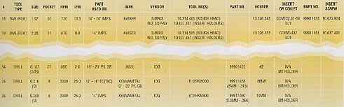
Figure 1: Compiling detailed lists about tools and their optimal cutting parameters helps to make machining processes more consistent. Programmers can use the lists to specify speeds based on historical data, not guesses.
The next two columns indicate the rpm and ipm that have proved to work best. This data tells everyone how a particular tool should be run. Programmers, manufacturing engineers, supervisors and operators can all see what speeds and feeds were used to set up a process.
Another important bit of information that we include is which part or parts a particular tool is used for. This makes it easy to see what impact changing a tool has on other processes that run on the same machine. For example, switching to an extended-length holder may be acceptable on some parts but not on others.
The lists include the manufacturer and vendor for each tool, as well as the manufacturer’s part number. Some items have our own part numbers assigned to them, which lets us order them via our electronic purchasing system.
We also include information about the type and size of holder required for the machine, as well as the insert or collet—depending on the tool type—that has been specified by our manufacturing-engineering department.
These lists offer a number of benefits. One is that they accurately disseminate information about the tools that a shop uses. Our tool lists are posted on our internal computer network, making them readily available to anyone with a need for the information.
Making the data easy to retrieve helps prevent extended downtime. Sometimes a company will rely on one or two individuals to track all of its tooling requirements: what machine uses which insert, which vendor supplies the insert and so on. Resident experts are OK. But they can go on vacation or retire or quit or die. The production of parts must continue.
Compiling lists also lends continuity to machining processes. Programmers can write codes with speeds and feeds that are givens, not guesses.
And a list can serve as a benchmark for improving a process. For instance, let’s say that a shop has invited a supplier to its facility to demonstrate a cutting tool. The shop can make a more informed decision about whether or not to purchase the product if it has a detailed record of its existing tool’s capabilities.
Lastly, lists can help determine a shop’s tool inventory. By periodically analyzing its lists, a company can confidently weed out obsolete tooling. This occasional purging of the tool crib lessens the chance of operators utilizing the wrong tool for their processes.
Using the right tool the right way and compiling lists don’t guarantee crash-free cutting. But doing these things will make a process more consistent. And a consistent process is likelier to put parts on the floor every day. That leads to cost savings. Every day.
About the Author
Brent Chandler is tool design supervisor at Roots Division, Dresser Equipment Group Inc.—A Halliburton Company, Connersville, Ind.
Teach Machinists the Basics
Machinists that are given helpful information will do their part to make sure cutting tools are used effectively and not pushed too hard. A good place to start is the manufacturer’s recommended speeds and feeds.
These recommendations should be considered guidelines, not gospel. They are established under ideal machining conditions in controlled settings. Dealing with material problems, fighting the rigidity of the setup and struggling with chatter in extended-length tools are not things that the guys in the lab factor into their calculations.
But catalog numbers shouldn’t be ignored, either. Knowing a cutting tool’s potential allows a machine operator to push a process in those areas where gains can most likely be made.
As for preventing tool wipeout, make sure operators recognize and react to tool wear before it becomes excessive. No matter what approach you take to machining, an unmonitored tool will fail.
Many of the major manufacturers of carbide tools offer courses on how to recognize tool wear. Attendees are given written materials that are informative without being overly technical. Check with your tooling sales rep.
— B. Chandler
Related Glossary Terms
- boring
boring
Enlarging a hole that already has been drilled or cored. Generally, it is an operation of truing the previously drilled hole with a single-point, lathe-type tool. Boring is essentially internal turning, in that usually a single-point cutting tool forms the internal shape. Some tools are available with two cutting edges to balance cutting forces.
- boring machine
boring machine
Similar to a turning machine except that the cutting tool (single-point or multiple-cutting-edge), rather than the workpiece, rotates to perform internal cuts. However, boring can be accomplished by holding the tool stationary and turning the workpiece. Takes a variety of vertical, slanted and horizontal forms, and has one or more spindles. Typically a large, powerful machine, it can readily hold tolerances to 0.0001". See jig boring; lathe; turning machine.
- chatter
chatter
Condition of vibration involving the machine, workpiece and cutting tool. Once this condition arises, it is often self-sustaining until the problem is corrected. Chatter can be identified when lines or grooves appear at regular intervals in the workpiece. These lines or grooves are caused by the teeth of the cutter as they vibrate in and out of the workpiece and their spacing depends on the frequency of vibration.
- computer numerical control ( CNC)
computer numerical control ( CNC)
Microprocessor-based controller dedicated to a machine tool that permits the creation or modification of parts. Programmed numerical control activates the machine’s servos and spindle drives and controls the various machining operations. See DNC, direct numerical control; NC, numerical control.
- coolant
coolant
Fluid that reduces temperature buildup at the tool/workpiece interface during machining. Normally takes the form of a liquid such as soluble or chemical mixtures (semisynthetic, synthetic) but can be pressurized air or other gas. Because of water’s ability to absorb great quantities of heat, it is widely used as a coolant and vehicle for various cutting compounds, with the water-to-compound ratio varying with the machining task. See cutting fluid; semisynthetic cutting fluid; soluble-oil cutting fluid; synthetic cutting fluid.
- depth of cut
depth of cut
Distance between the bottom of the cut and the uncut surface of the workpiece, measured in a direction at right angles to the machined surface of the workpiece.
- feed
feed
Rate of change of position of the tool as a whole, relative to the workpiece while cutting.
- fixture
fixture
Device, often made in-house, that holds a specific workpiece. See jig; modular fixturing.
- flutes
flutes
Grooves and spaces in the body of a tool that permit chip removal from, and cutting-fluid application to, the point of cut.
- high-speed steels ( HSS)
high-speed steels ( HSS)
Available in two major types: tungsten high-speed steels (designated by letter T having tungsten as the principal alloying element) and molybdenum high-speed steels (designated by letter M having molybdenum as the principal alloying element). The type T high-speed steels containing cobalt have higher wear resistance and greater red (hot) hardness, withstanding cutting temperature up to 1,100º F (590º C). The type T steels are used to fabricate metalcutting tools (milling cutters, drills, reamers and taps), woodworking tools, various types of punches and dies, ball and roller bearings. The type M steels are used for cutting tools and various types of dies.
- inches per minute ( ipm)
inches per minute ( ipm)
Value that refers to how far the workpiece or cutter advances linearly in 1 minute, defined as: ipm = ipt 5 number of effective teeth 5 rpm. Also known as the table feed or machine feed.
- milling machine ( mill)
milling machine ( mill)
Runs endmills and arbor-mounted milling cutters. Features include a head with a spindle that drives the cutters; a column, knee and table that provide motion in the three Cartesian axes; and a base that supports the components and houses the cutting-fluid pump and reservoir. The work is mounted on the table and fed into the rotating cutter or endmill to accomplish the milling steps; vertical milling machines also feed endmills into the work by means of a spindle-mounted quill. Models range from small manual machines to big bed-type and duplex mills. All take one of three basic forms: vertical, horizontal or convertible horizontal/vertical. Vertical machines may be knee-type (the table is mounted on a knee that can be elevated) or bed-type (the table is securely supported and only moves horizontally). In general, horizontal machines are bigger and more powerful, while vertical machines are lighter but more versatile and easier to set up and operate.
- tapping
tapping
Machining operation in which a tap, with teeth on its periphery, cuts internal threads in a predrilled hole having a smaller diameter than the tap diameter. Threads are formed by a combined rotary and axial-relative motion between tap and workpiece. See tap.
- toolchanger
toolchanger
Carriage or drum attached to a machining center that holds tools until needed; when a tool is needed, the toolchanger inserts the tool into the machine spindle. See automatic toolchanger.
- turning
turning
Workpiece is held in a chuck, mounted on a face plate or secured between centers and rotated while a cutting tool, normally a single-point tool, is fed into it along its periphery or across its end or face. Takes the form of straight turning (cutting along the periphery of the workpiece); taper turning (creating a taper); step turning (turning different-size diameters on the same work); chamfering (beveling an edge or shoulder); facing (cutting on an end); turning threads (usually external but can be internal); roughing (high-volume metal removal); and finishing (final light cuts). Performed on lathes, turning centers, chucking machines, automatic screw machines and similar machines.