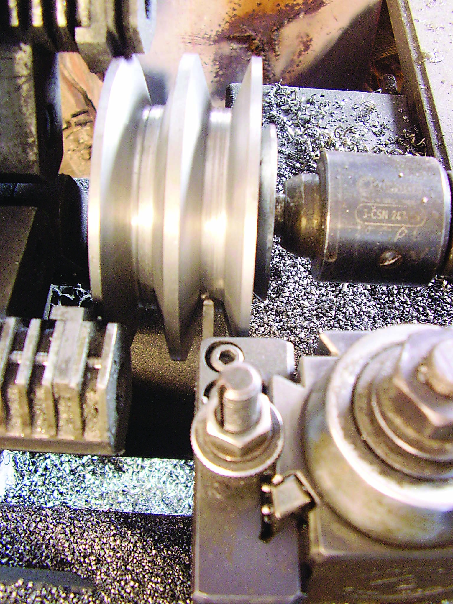
In this article, I’ll talk about making grooves for V-belts on a lathe. The first photograph shows a two-groove cast-iron sheave with 34-degree grooves in the manufacturing process. I use a brazed-carbide T-type cutoff blade for this work.
I put a full-radius nose with a positive rake angle on the carbide. The positive rake angle makes for faster metal removal and a nice surface finish. When I make a groove, I make a rectangular cutout that forms the depth of the groove, and then I cut the flank angles. I make a few parallel plunges to get to the width at the bottom of the groove. Then the flanks of the groove are formed.
I make the rectangular cutout in steps. First, I plunge the tool along the x-axis to a depth four times the width of the tool. Next, I retract the tool and move on the z-axis three-fourths the width of the tool, staying in the rectangular cut area. Then I make a cut to a depth eight times the width of the tool. For the next cut, I retract, move on the z-axis another three-fourths the tool width and cut to 12 times the tool width. I repeat this procedure until the groove depth is reached and there is a bumpy bottom to the groove, then I move in the z direction to clean the groove bottom.
This technique is handy when parting off a large-diameter piece. Make the parting groove width 1.75 times the tool width by moving the tool back and forth in the groove and taking progressively deeper cuts. It saves trouble from a tool jamming in the work and possibly breaking.
When cutting the flanks, make cuts with the nose of the tool. With a CNC machine or a manual machine with a compound cross slide, the procedure is similar. Step in the z direction and make cuts at 17 degrees till the groove width is done and the surface finish is nice.
The radius on the nose causes chips to curl toward the center of the nose radius and makes for good chip evacuation from the cut. Some radius on the nose corners of the tool is important. If the tool has a square nose, chips tend to get caught between the side of the cutting tool and the side of the groove and cause trouble. This is especially important with stringy material like aluminum.
Using a wider tool makes for lateral stiffness, and then the tool can be used to profile the groove. The tool in the photos was the width I wanted but was too high for the toolholder used with the lathe, so the height was ground to fit the toolholder and make a nice, stiff setup. The second photo shows the tool in its holder. There is a piece of 3-thousandths-thick aluminum shim stock on top of the tool. That is so the toolholder clamp mechanism won’t crack the carbide.
Related Glossary Terms
- computer numerical control ( CNC)
computer numerical control ( CNC)
Microprocessor-based controller dedicated to a machine tool that permits the creation or modification of parts. Programmed numerical control activates the machine’s servos and spindle drives and controls the various machining operations. See DNC, direct numerical control; NC, numerical control.
- cutoff
cutoff
Step that prepares a slug, blank or other workpiece for machining or other processing by separating it from the original stock. Performed on lathes, chucking machines, automatic screw machines and other turning machines. Also performed on milling machines, machining centers with slitting saws and sawing machines with cold (circular) saws, hacksaws, bandsaws or abrasive cutoff saws. See saw, sawing machine; turning.
- cutoff blade
cutoff blade
Blade mounted on a shank or arbor and held in a milling-machine spindle for simple cutoff tasks.
- lathe
lathe
Turning machine capable of sawing, milling, grinding, gear-cutting, drilling, reaming, boring, threading, facing, chamfering, grooving, knurling, spinning, parting, necking, taper-cutting, and cam- and eccentric-cutting, as well as step- and straight-turning. Comes in a variety of forms, ranging from manual to semiautomatic to fully automatic, with major types being engine lathes, turning and contouring lathes, turret lathes and numerical-control lathes. The engine lathe consists of a headstock and spindle, tailstock, bed, carriage (complete with apron) and cross slides. Features include gear- (speed) and feed-selector levers, toolpost, compound rest, lead screw and reversing lead screw, threading dial and rapid-traverse lever. Special lathe types include through-the-spindle, camshaft and crankshaft, brake drum and rotor, spinning and gun-barrel machines. Toolroom and bench lathes are used for precision work; the former for tool-and-die work and similar tasks, the latter for small workpieces (instruments, watches), normally without a power feed. Models are typically designated according to their “swing,” or the largest-diameter workpiece that can be rotated; bed length, or the distance between centers; and horsepower generated. See turning machine.
- parallel
parallel
Strip or block of precision-ground stock used to elevate a workpiece, while keeping it parallel to the worktable, to prevent cutter/table contact.
- parting
parting
When used in lathe or screw-machine operations, this process separates a completed part from chuck-held or collet-fed stock by means of a very narrow, flat-end cutting, or parting, tool.
- rake
rake
Angle of inclination between the face of the cutting tool and the workpiece. If the face of the tool lies in a plane through the axis of the workpiece, the tool is said to have a neutral, or zero, rake. If the inclination of the tool face makes the cutting edge more acute than when the rake angle is zero, the rake is positive. If the inclination of the tool face makes the cutting edge less acute or more blunt than when the rake angle is zero, the rake is negative.
- stiffness
stiffness
1. Ability of a material or part to resist elastic deflection. 2. The rate of stress with respect to strain; the greater the stress required to produce a given strain, the stiffer the material is said to be. See dynamic stiffness; static stiffness.
- toolholder
toolholder
Secures a cutting tool during a machining operation. Basic types include block, cartridge, chuck, collet, fixed, modular, quick-change and rotating.
Author

Brandt Taylor is owner of Berlin, Massachusetts-based Taylor Engineering, a machine shop.
