The moving elements of a machine tool have mass. Forces from the actuators cause the masses to move and accelerate. As the speed of the machine tool motion increases, the ability of the actuators to cause acceleration becomes more important.
Rather than the physical masses of the moving elements, the actuators see the “apparent masses” of moving elements, which are often significantly less.

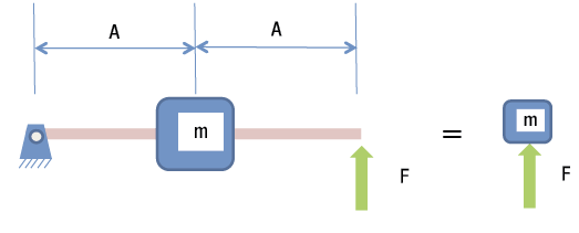
Figure 1. An actuator sees the apparent mass of moving elements instead of the physical mass. All images courtesy S. Smith.
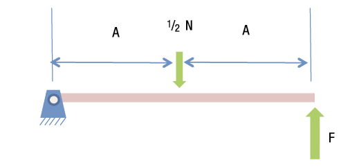
Figure 2. Summing the moments around the pin determines the applied force.
A force (F) applied to a mass (m) causes an acceleration (A), according to the formula F = mA. One way to measure mass is by measuring the force required to cause acceleration. The ratio between the acceleration and the applied force is the mass (F/A = m).
In Figure 1, the physical mass is attached to the middle of a rigid bar. The left end of the bar is attached to the ground, but allowed to pivot. The actuator applying the force is at the right end of the bar. From the actuator’s perspective, the bar does not exist. Instead, there appears to be a mass resisting the applied force, as shown to the right.
But how large is that apparent mass? If the applied force causes an acceleration of 1 m/sec.2 at the right end of the bar, the acceleration at the middle of the bar where the mass is attached is ½ m/sec.2. If the mass is 1 kg, the force caused by the mass resisting the acceleration at the middle of the bar causes a force of ½ N on the bar at its midpoint.
To find the force required from the actuator to create this situation, sum the moments around the pin (Figure 2). The equation is:
½ N × A – F × 2A = 0
Solving for F gives ¼ N. From the actuator’s point of view, ¼ N is required to cause 1 m/sec.2 at the right end of the bar. To the actuator, it seems there is a mass of ¼ kg—the apparent mass—located at the actuator, even though the physical mass is 1 kg. The apparent mass is different than the physical mass by the square of the transmission ratio.
The transmission ratio (½, or 1:2) appears initially because the mass has less acceleration than the end of the bar and appears again because the actuator has the mechanical advantage of the lever. If the mass was located a third of the way from the pivot to the end of the bar, the apparent mass at the actuator would be 1⁄9 kg. If the mass was at the end of the bar, and the actuator was attached to the midpoint, the apparent mass would be 4 kg.
So how does this apply to machine tool motion? In most machine tools, a servomotor attached to a ballscrew and nut drives the moving elements. There is typically a high transmission ratio for the ballscrew because many turns of the screw are required to cause a small linear motion of the slide. The mass of the moving elements are reflected back to the servomotor as a rotary inertia through the square of the transmission ratio. From the servomotor’s point of view, that means the inertia caused by the moving slide and workpiece seems small.
The presence or absence of the workpiece and the changing mass of the workpiece during machining typically have little impact on the apparent inertia as seen by the servomotor. In most cases, the main sources of the apparent inertia at the servomotor are the inertia of the servomotor rotor and the attached ballscrew. This is generally desired because it means the workpiece does not change machine tool performance.
Author
Dr. Scott Smith is a professor and chair of the Department of Mechanical Engineering at the William States Lee College of Engineering, University of North Carolina at Charlotte, specializing in machine tool structural dynamics. Contact him via e-mail at [email protected].

Click on the author to view all of their articles!