Since the May issue, I have been writing about our combustion shop’s migration from batch processing to single-piece flow, or machining one part at a time. Single-piece flow eliminates work in process. This is desirable because WIP hides part defects and increases lead times and inventory levels.
As part of our single-piece flow process, we have arranged each of the machines’ tool magazines to have common tools. This allows us to run a program created for one vertical machining center on any VMC without resetting the tool magazine or changing the program. Horizontal machining centers are set up the same way. This arrangement means operators do not need to alter the tool magazine before they begin machining, allowing them to quickly move to the next operation.
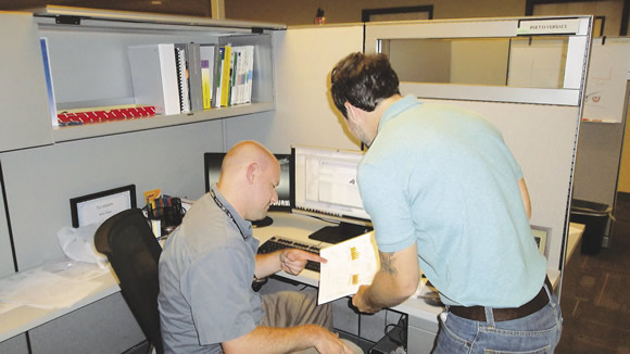
NC Programmer Rocco Versace (right) and Component Engineer Matt Sealy discuss the CNC program, CAD models and documentation for a project.
Properly documenting processing steps and making the documentation readily available to operators is critical to implementing single-piece flow. Our manufacturing engineers work with the operators, NC programmers and fixture designers to plan and design the processes. Each of the part components and fixtures are modeled in CAD, allowing us to identify problems before a fixture is built. Once the fixture design is complete, models of the part and fixture are sent to the NC programmer.
Accurate models help reduce fixture rework and allow the NC programmer to produce more accurate CNC code, which helps reduce program prove-out time during the initial part run. Software that works in conjunction with our CAD system also allows us to utilize the models and create 3-D images of the setup, which can be viewed electronically or on paper, as well as create detailed instructions for operators.
At most large manufacturing companies like ours, engineers create instructions with detailed information about the part and setup so a part can be accurately reproduced. We refer to them as “work instructions” and provide a set for every operation in the plant. They are a critical component in our manufacturing process because accurate, concise instructions quickly tell an operator how to place the workpiece in a fixture and how to place the fixture in a machine tool.
All this careful planning and engineering, however, is ineffective if the operator cannot execute the plan. Incomplete or inaccurate instructions can cause the operator to seek answers and delay the start of a job. These delays negatively impact cycle times and can disrupt part flow to subsequent operations, possibly delaying other processes. It is important that the instructions accurately convey the process and all operators understand them.
Implementing single-piece flow takes time but it will improve lead times, increase flexibility and reduce setup times and WIP. The process may seem daunting but it is applicable in many shops.
Smaller shops, however, are often forced into batch processing because customers submit orders for a fixed quantity at irregular intervals or order parts only once. But those shops can still adopt concepts similar to our plan to achieve efficiency gains. The following are some examples.
n Creative approaches to CNC programming and cutting tool application can reduce the number of tools needed to complete jobs.
n Analyzing which tools are used the most and keeping them in a magazine can help reduce setup time.
n Placing a subplate on a table that allows workholders to be accurately placed can eliminate the need to align the fixture to the machine tool.
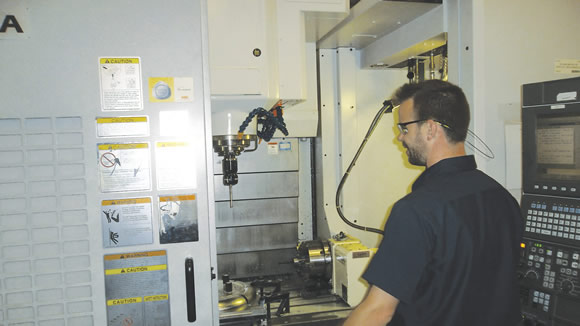
Joel Johnson, team leader for machining in the combustion shop, prepares to run a program created by Rocco Versace on an Okuma VMC.
n When multiple setups are required to complete a part, it might be practical to simultaneously run sequential operations on multiple machine tools. Creating work cells can make this easier.
n Investing in a machine tool that has more axes of motion can eliminate the need to transfer parts from one type of machine to another.
Ultimately, we are trying to reduce waste by eliminating activities that do not add value to a part. Competition sets the price a customer is willing to pay for a part. To increase profit margins, you need to reduce setup times and tooling inventory, eliminate operations, reduce cycle times and compress the time lapse from order to invoice.
Walk your shop, view the daily activity and ask yourself, “Would a customer pay me to do that?” If the answer is no, you’ve probably found an opportunity to reduce waste. CTE
About the Author: Christopher Tate is manufacturing engineering lead for machining at Mitsubishi Power Systems, Savannah (Ga.) Machinery Works, a global builder of gas and steam turbines. He holds a Master of Science and Bachelor of Science from Mississippi State University. E-mail: [email protected].Related Glossary Terms
- 3-D
3-D
Way of displaying real-world objects in a natural way by showing depth, height and width. This system uses the X, Y and Z axes.
- centers
centers
Cone-shaped pins that support a workpiece by one or two ends during machining. The centers fit into holes drilled in the workpiece ends. Centers that turn with the workpiece are called “live” centers; those that do not are called “dead” centers.
- computer numerical control ( CNC)
computer numerical control ( CNC)
Microprocessor-based controller dedicated to a machine tool that permits the creation or modification of parts. Programmed numerical control activates the machine’s servos and spindle drives and controls the various machining operations. See DNC, direct numerical control; NC, numerical control.
- computer-aided design ( CAD)
computer-aided design ( CAD)
Product-design functions performed with the help of computers and special software.
- fixture
fixture
Device, often made in-house, that holds a specific workpiece. See jig; modular fixturing.
- machining center
machining center
CNC machine tool capable of drilling, reaming, tapping, milling and boring. Normally comes with an automatic toolchanger. See automatic toolchanger.
- numerical control ( NC)
numerical control ( NC)
Any controlled equipment that allows an operator to program its movement by entering a series of coded numbers and symbols. See CNC, computer numerical control; DNC, direct numerical control.
Author

Christopher Tate is the owner of Tate Engineering, a Natchez, Mississippi, firm that helps manufacturers solve efficiency problems. Tate, who earned master's degree in industrial technology from Mississippi State University, has 32 years of experience in the metalworking industry.