TDM 4.6 Tool Data Management Software
TDM 4.6 Tool Data Management Software
TDM Systems presents the new release of its tool data management software, TDM 4.6.
TDM Systems presents the new release of its tool data management software, TDM 4.6. The TDM developers have again targeted the effort required to implement the tool and resource management system and ease of usability: Shorter implementation times, easier understanding and global use is the motto. TDM 4.6 also forms the basis for the completely new "Global Line" products for global use across various locations.
"We have already spent many years working intensively on simplifying our comprehensive tool management software, whether for installation or for ease of use," says Eugen Bollinger, Sales Director at TDM Systems. "On the one hand, our customers need full functionality, however, that must not impact lead times and usability."
Therefore, TDM Systems has been specifically running the "Easy Start with TDM" project initiative for some time now. This had already lead to many ways of simplifying implementation in the past.
The TDM developers have improved the 3D generators further and thereby stream lining CAM simulation: A 3D-Revolve Generator for rotationally symmetric tools, as well as a 3D-Solid Converter on the leading CAM systems accelerate process simulation and collision analysis. In addition, the company has focused its attention on tool data exchange and usability.
"Everything should become even easier for our users in the future, as it only takes a few mouse clicks to go from importing data to simulation support and then to providing data on presetting devices and CNC machines," Bollinger says.
Easy start by using the automated data import function TDM 4.6 now offers a "Data Downloader" for Walter tools and a "Tool Loader" for tools from other manufacturers, in order to ensure the database is filled from the very start as quickly as possible. For example, from now on, if you require data for Walter tools, you can very easily download the data from the Internet into TDM at the click of a mouse using the Walter Data Downloader. The advantage of this is that, along with the master data, you are provided with simulation data, 2D and 3D graphics at the same time. And the highlight here is that the Downloader automatically loads the data on the selected tools directly into TDM.
Bollinger says: "Our users, whether in NC programming, tool presetting or on the machine, want quick access to their tool data, feeds and speeds, and we are simplifying this over the long term with version 4.6."
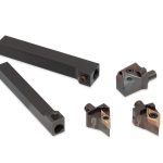
Regardless of whether you choose the TDM Tool Loader or the online download from the manufacturer, the same applies: When creating the data, the ident number, designation and CAD number of the tools can be generated automatically. Alternatively, you can, of course, specify this information manually. The tools are assigned to the corresponding class or group; characteristics, such as geometry data and cut-off areas for the automatic assembly of tools are also set by the system.
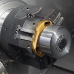
How important a production-related and realistic simulation with accurate tool data, feeds and speeds in CAD/CAM is, can be seen in practice on a daily basis. Anyone who carries out collision analyses with tool dummies is taking a risk, because interference contours are sometimes not detected at all. Process reliability is at risk. When it comes to CAD/CAM connections, TDM is certainly leading the way with its powerful 3D Graphic Generators. According to the company, the new 3D Revolve Generator for drilling tools and milling cutters and the 3D Graphic Converter have what it takes. Only a few mouse clicks later and the programmer has used the 3D Revolve Generator to create a realistic 3D model on his computer screen from 2D data in dxf format. The models can be saved as STEP files and therefore do not need to be regenerated repeatedly. The principle is simple: Using the 2D data and the Tool Contour Generator, the outline contour is generated. Now it only needs to be rotated and the Revolve Generator creates the simulation-ready 3D solid model from the tool outline. In this way, 3D models can be quickly and conveniently generated on the basis of existing 2D drawings. TDM version 4.6 has a new 3D Solid Converter that ensures the rotating solids subsequently fit the CAD/CAM system used. There is 3D data in STEP format to support the CAM systems NX, ProE, TopSolidCAM, ESPRIT, CATIA, Vericut, WinFlex and Exapt.
"This allows us to achieve additional process reliability in production because the simulated 3D models are more exact and more realistic than the pure parametric models," emphasizes Bollinger.
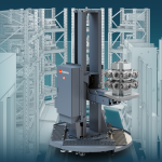
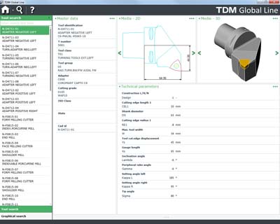
What is known as data mapping also comes into play here: Once generated, a 3D model is mapped to the remaining CAM systems. TDM Systems will be in a position to support international and globally active companies, who need access via a central system, even better in the future. The new "TDM Global Line" module series makes connecting global locations much easier. The new "TDM Global Line" product line offers a high-performance and future-proof solution for managing tool items, tool assemblies, and tool lists, as well as for tool crib entries. The modules are designed for global use, so that operations can be conveniently carried out in conjunction with the comprehensive TDM V4 product portfolio. An important highlight here is that from now on, users can update and maintain their tool data live in the system from anywhere. The updated tool data and feeds and speeds, including tool lists, are immediately usable and accessible worldwide. Thanks to the use of a dedicated application server, TDM Global Line can be scaled very easily and runs on the same database as the basic installation. The transmission of data worldwide is fully encrypted and is also compressed to ensure the data can be accessed quickly.