Mastercam 2019 CAD/CAM Software

June 25, 2018
Mastercam 2019 CAD/CAM Software

CNC Software Inc. announces the release of Mastercam 2019. It is available for purchase. Mastercam 2019 was developed to streamline the manufacturing process from job setup to job completion. Mastercam 2019 increases machining productivity and reduces overall production costs with new 2D through multiaxis milling automation features, CAD and model preparation improvements, expanded 3D tooling, Accelerated Finishing and powerful turning and Mill-Turn enhancements.

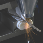
Mastercam 2019 continues to increase productivity and programming efficiency, while reducing overall production costs, with a series of automated 2D through 5-axis toolpath improvements. Re-engineered chamfering and holemaking strategies, plus the new Multiaxis deburring provide new levels of time-saving automation and simplicity. New milling toolpath strategies, like the high speed Equal Scallop toolpath, offer both machining performance and surface finish improvements. The new release includes additional support for the Sandvik Coromant PrimeTurning method, enhanced grooving, bar feed, and other features for turning and mill-turn applications, plus new lathe and Swiss-style machine support.


Mastercam 2019 increases efficiency and reduces job setup time and the preparation needed for part machining and programming. This includes enhanced CAD functionality and 3D model import support, improved part preparation and fixture setup tools, additional PowerSurface capabilities, and expanded support for Model-Based Definition (MBD).

Mastercam 2019’s expanded digital tool library capability delivers accurate, 3D tool assembly models, with access to the latest cutting tool technology and updates for Sandvik Coromant CoroPlus and MachiningCloud platforms. Mastercam 2019 also expands Accelerated Finishing with support for taper and lens style tools aimed at 75 percent cycle time improvement for finishing operations with superior surface finish quality.

With improvements to toolpath and machine simulation, toolpath graphics, and other verification and analysis tools, Mastercam 2019 provides greater programming assurance and allows for better, more informed decisions before a job is run. These improvements include support for block drilling multiple holes simultaneously and better axis control in simulation, allowing you to easily check machine limits or collision checking.

Mastercam 2019 also improves job documentation and management, while helping to address quality and certification initiatives. New toolpath visualization capabilities and section view tools, improvements to view and setup sheets, and a wide array of system level enhancements improve efficiency in managing job workflow, as well as providing better tools for process documentation.

Related Glossary Terms

  • chamfering

    chamfering

    Machining a bevel on a workpiece or tool; improves a tool’s entrance into the cut.

  • computer numerical control ( CNC)

    computer numerical control ( CNC)

    Microprocessor-based controller dedicated to a machine tool that permits the creation or modification of parts. Programmed numerical control activates the machine’s servos and spindle drives and controls the various machining operations. See DNC, direct numerical control; NC, numerical control.

  • computer-aided design ( CAD)

    computer-aided design ( CAD)

    Product-design functions performed with the help of computers and special software.

  • feed

    feed

    Rate of change of position of the tool as a whole, relative to the workpiece while cutting.

  • fixture

    fixture

    Device, often made in-house, that holds a specific workpiece. See jig; modular fixturing.

  • gang cutting ( milling)

    gang cutting ( milling)

    Machining with several cutters mounted on a single arbor, generally for simultaneous cutting.

  • grooving

    grooving

    Machining grooves and shallow channels. Example: grooving ball-bearing raceways. Typically performed by tools that are capable of light cuts at high feed rates. Imparts high-quality finish.

  • lathe

    lathe

    Turning machine capable of sawing, milling, grinding, gear-cutting, drilling, reaming, boring, threading, facing, chamfering, grooving, knurling, spinning, parting, necking, taper-cutting, and cam- and eccentric-cutting, as well as step- and straight-turning. Comes in a variety of forms, ranging from manual to semiautomatic to fully automatic, with major types being engine lathes, turning and contouring lathes, turret lathes and numerical-control lathes. The engine lathe consists of a headstock and spindle, tailstock, bed, carriage (complete with apron) and cross slides. Features include gear- (speed) and feed-selector levers, toolpost, compound rest, lead screw and reversing lead screw, threading dial and rapid-traverse lever. Special lathe types include through-the-spindle, camshaft and crankshaft, brake drum and rotor, spinning and gun-barrel machines. Toolroom and bench lathes are used for precision work; the former for tool-and-die work and similar tasks, the latter for small workpieces (instruments, watches), normally without a power feed. Models are typically designated according to their “swing,” or the largest-diameter workpiece that can be rotated; bed length, or the distance between centers; and horsepower generated. See turning machine.

  • milling

    milling

    Machining operation in which metal or other material is removed by applying power to a rotating cutter. In vertical milling, the cutting tool is mounted vertically on the spindle. In horizontal milling, the cutting tool is mounted horizontally, either directly on the spindle or on an arbor. Horizontal milling is further broken down into conventional milling, where the cutter rotates opposite the direction of feed, or “up” into the workpiece; and climb milling, where the cutter rotates in the direction of feed, or “down” into the workpiece. Milling operations include plane or surface milling, endmilling, facemilling, angle milling, form milling and profiling.

  • toolpath( cutter path)

    toolpath( cutter path)

    2-D or 3-D path generated by program code or a CAM system and followed by tool when machining a part.

  • turning

    turning

    Workpiece is held in a chuck, mounted on a face plate or secured between centers and rotated while a cutting tool, normally a single-point tool, is fed into it along its periphery or across its end or face. Takes the form of straight turning (cutting along the periphery of the workpiece); taper turning (creating a taper); step turning (turning different-size diameters on the same work); chamfering (beveling an edge or shoulder); facing (cutting on an end); turning threads (usually external but can be internal); roughing (high-volume metal removal); and finishing (final light cuts). Performed on lathes, turning centers, chucking machines, automatic screw machines and similar machines.