GibbsCAM 2012+

August 13, 2012

Gibbs and Associates announced the release of the latest version of GibbsCAM CNC programming software. Called GibbsCAM 2012+, this new version includes speed and performance improvements, including a rendering option specifically geared for multi-axis parts, improved cutting strategies and many productivity enhancements. The new version includes improvements for all levels of GibbsCAM, including the Mill and Lathe Production, SolidSurfacer, Radial Milling, MTM and 5-Axis options.

The software includes a Multi-Axis Rendering option free of charge with each seat of the software. Formerly a $2,000 option, Multi-Axis Rendering provides significant accuracy improvements for rotary milling applications, especially when displaying toolpaths with continuous changes in both tool position and orientation. Improved gouge and tool interference checking for tilting tools shows customers programming errors before they become costly mistakes on the shop floor.

To boost speed and productivity for all GibbsCAM users, the GibbsCAM 2012+ rendering engine takes advantage of multi-core and multi-threaded computer hardware to drastically boost processing speed. Part rendering speed is now up to 33 times faster, depending on specific computer hardware and part complexity. Increased rendering speed saves programming time and reduces programming costs.

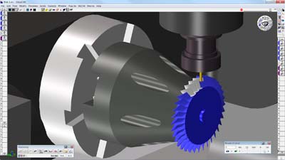
Improvements to Radial Milling include the ability to produce a smooth, unsegmented, helical toolpath, which takes advantage of native machine-based linear and circular interpolation capabilities. The benefits of this type of toolpath include simplified post-processor output, potential savings of hundreds of lines of G-code, and reduced machining time. Also included are new cutting strategies for parts with open-sided pockets, very thin walls, shallow cut areas and a highly efficient G-code program. In addition, material only clean-up areas provide customers with optimized toolpaths.

Related Glossary Terms

  • computer numerical control ( CNC)

    computer numerical control ( CNC)

    Microprocessor-based controller dedicated to a machine tool that permits the creation or modification of parts. Programmed numerical control activates the machine’s servos and spindle drives and controls the various machining operations. See DNC, direct numerical control; NC, numerical control.

  • gang cutting ( milling)

    gang cutting ( milling)

    Machining with several cutters mounted on a single arbor, generally for simultaneous cutting.

  • interpolation

    interpolation

    Process of generating a sufficient number of positioning commands for the servomotors driving the machine tool so the path of the tool closely approximates the ideal path. See CNC, computer numerical control; NC, numerical control.

  • lathe

    lathe

    Turning machine capable of sawing, milling, grinding, gear-cutting, drilling, reaming, boring, threading, facing, chamfering, grooving, knurling, spinning, parting, necking, taper-cutting, and cam- and eccentric-cutting, as well as step- and straight-turning. Comes in a variety of forms, ranging from manual to semiautomatic to fully automatic, with major types being engine lathes, turning and contouring lathes, turret lathes and numerical-control lathes. The engine lathe consists of a headstock and spindle, tailstock, bed, carriage (complete with apron) and cross slides. Features include gear- (speed) and feed-selector levers, toolpost, compound rest, lead screw and reversing lead screw, threading dial and rapid-traverse lever. Special lathe types include through-the-spindle, camshaft and crankshaft, brake drum and rotor, spinning and gun-barrel machines. Toolroom and bench lathes are used for precision work; the former for tool-and-die work and similar tasks, the latter for small workpieces (instruments, watches), normally without a power feed. Models are typically designated according to their “swing,” or the largest-diameter workpiece that can be rotated; bed length, or the distance between centers; and horsepower generated. See turning machine.

  • milling

    milling

    Machining operation in which metal or other material is removed by applying power to a rotating cutter. In vertical milling, the cutting tool is mounted vertically on the spindle. In horizontal milling, the cutting tool is mounted horizontally, either directly on the spindle or on an arbor. Horizontal milling is further broken down into conventional milling, where the cutter rotates opposite the direction of feed, or “up” into the workpiece; and climb milling, where the cutter rotates in the direction of feed, or “down” into the workpiece. Milling operations include plane or surface milling, endmilling, facemilling, angle milling, form milling and profiling.

  • milling machine ( mill)

    milling machine ( mill)

    Runs endmills and arbor-mounted milling cutters. Features include a head with a spindle that drives the cutters; a column, knee and table that provide motion in the three Cartesian axes; and a base that supports the components and houses the cutting-fluid pump and reservoir. The work is mounted on the table and fed into the rotating cutter or endmill to accomplish the milling steps; vertical milling machines also feed endmills into the work by means of a spindle-mounted quill. Models range from small manual machines to big bed-type and duplex mills. All take one of three basic forms: vertical, horizontal or convertible horizontal/vertical. Vertical machines may be knee-type (the table is mounted on a knee that can be elevated) or bed-type (the table is securely supported and only moves horizontally). In general, horizontal machines are bigger and more powerful, while vertical machines are lighter but more versatile and easier to set up and operate.

  • toolpath( cutter path)

    toolpath( cutter path)

    2-D or 3-D path generated by program code or a CAM system and followed by tool when machining a part.