CNC Training Includes 5-axis Simulation

June 19, 2020
CNC 5-Axis Simulation Training Addresses Manufacturing Skills Gap

To further develop the next-gen manufacturing workforce, FANUC America, a leading automation solutions provider, is expanding its CNC training offerings to include 5-axis simulation. 
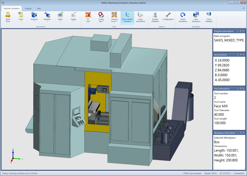
FANUC’s Machining Simulation for Workforce Development provides training for controls operation and part programming in a virtual environment. The Complex Milling Extension option combines FANUC’s CNC Guide and simulation software that can now operate as one of the three main 5-axis mill kinematics.  The offering also includes training on a 3-axis mill and a 2-axis lathe for maximum configuration flexibility. Via a digital twin, the 5-axis machining simulation allows users to learn how to setup and operate three common advanced 5-axis milling machines: mixed type, tool type and table type.  

Growing interest in 5-axis machining continues as more operations look to produce complex parts used in high-tech industries, such as aerospace and medical devices. As this sector of the machine tool business increases, the demand for 5-axis operators will exponentially grow. Finding qualified workers to fill these positions will challenge many employers, who are already facing a tight labor market due to the widely known manufacturing skills gap issue.

Training new or existing workers in an effective and innovative way will be key to bridging this gap. FANUC is committed to working with industry as well as educational partners to help fill the growing 5-axis training demand. 

The addition of 5-axis simulation offers an immersive environment to practice and understand advanced machining techniques. Since 5-axis machining involves more complex machine setups, the simulation software effectively teaches users how to take advantage of the unique options and features. Additionally, the 5-axis machining simulation software allows operators to experiment with and prove out the machine setup and/or part program before modifying the actual machine.  

Related Glossary Terms

  • computer numerical control ( CNC)

    computer numerical control ( CNC)

    Microprocessor-based controller dedicated to a machine tool that permits the creation or modification of parts. Programmed numerical control activates the machine’s servos and spindle drives and controls the various machining operations. See DNC, direct numerical control; NC, numerical control.

  • gang cutting ( milling)

    gang cutting ( milling)

    Machining with several cutters mounted on a single arbor, generally for simultaneous cutting.

  • lathe

    lathe

    Turning machine capable of sawing, milling, grinding, gear-cutting, drilling, reaming, boring, threading, facing, chamfering, grooving, knurling, spinning, parting, necking, taper-cutting, and cam- and eccentric-cutting, as well as step- and straight-turning. Comes in a variety of forms, ranging from manual to semiautomatic to fully automatic, with major types being engine lathes, turning and contouring lathes, turret lathes and numerical-control lathes. The engine lathe consists of a headstock and spindle, tailstock, bed, carriage (complete with apron) and cross slides. Features include gear- (speed) and feed-selector levers, toolpost, compound rest, lead screw and reversing lead screw, threading dial and rapid-traverse lever. Special lathe types include through-the-spindle, camshaft and crankshaft, brake drum and rotor, spinning and gun-barrel machines. Toolroom and bench lathes are used for precision work; the former for tool-and-die work and similar tasks, the latter for small workpieces (instruments, watches), normally without a power feed. Models are typically designated according to their “swing,” or the largest-diameter workpiece that can be rotated; bed length, or the distance between centers; and horsepower generated. See turning machine.

  • milling

    milling

    Machining operation in which metal or other material is removed by applying power to a rotating cutter. In vertical milling, the cutting tool is mounted vertically on the spindle. In horizontal milling, the cutting tool is mounted horizontally, either directly on the spindle or on an arbor. Horizontal milling is further broken down into conventional milling, where the cutter rotates opposite the direction of feed, or “up” into the workpiece; and climb milling, where the cutter rotates in the direction of feed, or “down” into the workpiece. Milling operations include plane or surface milling, endmilling, facemilling, angle milling, form milling and profiling.

  • milling machine ( mill)

    milling machine ( mill)

    Runs endmills and arbor-mounted milling cutters. Features include a head with a spindle that drives the cutters; a column, knee and table that provide motion in the three Cartesian axes; and a base that supports the components and houses the cutting-fluid pump and reservoir. The work is mounted on the table and fed into the rotating cutter or endmill to accomplish the milling steps; vertical milling machines also feed endmills into the work by means of a spindle-mounted quill. Models range from small manual machines to big bed-type and duplex mills. All take one of three basic forms: vertical, horizontal or convertible horizontal/vertical. Vertical machines may be knee-type (the table is mounted on a knee that can be elevated) or bed-type (the table is securely supported and only moves horizontally). In general, horizontal machines are bigger and more powerful, while vertical machines are lighter but more versatile and easier to set up and operate.