It can be done, but it takes specific tools and special measures.
Deep-hole tapping may be the most problem-prone of all machining operations. Broken tools, premature tap wear, and damaged workpieces are constant threats.
Despite these difficulties, it is possible to tap deep holes successfully. But the machinist must know exactly under what conditions the tap will be cutting and carefully choose a tool specifically designed for those conditions.
Before we look for the proper deep-hole tapping tool, we must first consider the question: “How deep is deep?” If machinists are to avoid or alleviate the problems associated with deep-hole tapping, they must have some guide to tell them when the depth of the hole to be tapped calls for greater care and concern. The many variables that must be considered when tapping make it impossible to give an absolute answer. But it is possible to establish a working definition.
For such a definition to be useful, it should be applicable even to operations using the most delicate taps. Observation and experience indicate that taps with diameters of 1/2" or smaller, especially those with coarse pitches, are more likely than larger taps to break or experience other problems in deep holes, such as abrasive wear, dulling, heat, and chipping. The small taps’ core diameters may not be enough to resist the higher torque of a deep-hole tapping operation. Coarse pitches make the operation even more difficult, because the thicker chips created by the coarse pitch increase the torque of the operation. A definition for deep-hole tapping that will preclude problems when tapping within this smaller size range should also be sufficient for larger sizes, which can cope better with tapping forces.
Data from the field has shown us where the depth of the hole begins to be a factor in tool failures. Most of this data covers the use of hand taps with plug chamfers, which have 3 to 5 chamfered teeth per land, because these taps (also known as general-purpose taps) are the most commonly used. Reports from users of smaller diameter general-purpose hand taps indicate that problems usually occur when the minimum full thread depth is 1 1/2 times the nominal diameter of the tap or deeper. A useful working definition of deep-hole tapping, then, would be any tapping operation in which thread depth is at least 1 1/2 times the nominal diameter of the tap.
When an operation calls for tapping at this depth, the operator should know that he will probably not be able to use standard tapping procedures. Either some aspect of the tap or the tapping conditions will need to be changed. Some operations will require a change in both the tap and the tapping conditions.
Dulled by Deep Holes
The most common failure modes of general-purpose taps in deep-hole applications, caused by dulling, are undersized threads, chipping, and breakage. Problems occur because the taps are in the cut for a long time. All factors that cause tools to wear during normal tapping are exaggerated in deep-hole operations because of the tool’s extended exposure to them: There is more heat, more abrasion, more dulling and chipping of the cutting edges, and greater restriction of coolant flow.
A standard hand tap’s geometry may contribute to the problem of chip control in a deep-hole operation. Hand taps are designed to store chips in their flutes rather than direct the chips upward or out ahead of the tap. As the thread is cut by the chamfer and the first full tooth of each land of the tap, chips accumulate in the flutes along the chamfered section of the tap. Eventually, the chips may obstruct the flutes and prevent coolant from reaching the bearing area at the cutting edge. The temperature and torque in the cut rise as the friction caused by the accumulation of chips increases dramatically and the diminished coolant flow fails to carry the heat away. Too many chips packed in the flutes, and the elevated temperature and torque, may cause the tap to dull prematurely or chip and break.
A user experiencing problems with dull hand taps can choose one of two simple remedies. One alternative would be to select a larger H-limit for the tap. The tool’s increased diameter will allow it to wear longer before it produces undersized threads. A second option would be to select a tap with a surface treatment such as titanium nitride or titanium carbonitride. These treatments enhance wear resistance by increasing the hardness of the tap surface and lowering the coefficient of friction.
Broken Tools
Sometimes, tools used for deep-hole tapping fail catastrophically. As the tap dulls because of packed chips, tapping torque increases until the tap breaks. Breakage isn’t automatically a signal that dulling is causing a chip-control problem. Galling, routine wear, and the hardness of the workpiece material also can cause a tap to chip and break. To look for evidence that chip-packing is causing the tool to break, the user should examine the section of the tap broken off in the hole. If the depth of the hole is causing a chip-control problem, chips will be packed into the flutes of the tap remnant.
Chip-packing can be cured, but the specific remedy will depend on the exact cause of the problem. Chips may pack in the flutes because the tap creates thick chips as it advances in a deep hole. Assuming that causes of chipping and breakage such as a misalignment of the tool and workpiece, a lack of machine rigidity, or some other setup error have been ruled out, other causes may include the creation of continuous chips, a large chip volume, galling, insufficient coolant volume or pressure in the chamfered section of the tap, or a combination of these factors.
 Figure 1: Switching from a tap with a plug chamfer (right) to a tap with a taper chamfer will produce chips that are easier for the tap to handle because they are half as thick. |
|
Chip-thickness problems can be solved by a change in the tap chamfer, if the hole is a through hole or a blind hole with sufficient depth beyond the threaded section. Changing from a general-purpose tap with 3 to 5 teeth per land to a hand tap with a taper chamfer that offers 8 to 10 teeth per land will cut chip thickness approximately in half (Figure 1). Although the same volume of chips will be produced by the tapping operation, the tap will be able to store these smaller chips more easily. The longer chamfer and additional teeth also reduce the chip load per tooth. With a diminished chip load, the tap is subject to less torsional stress, and the risk of tap breakage is reduced. Increasing the chamfer length also extends tap life substantially.
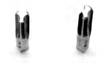 Figure 2: The 2-flute tap (right) can store more chips than the 3-flute tap, because the 2-flute configuration allows for wider and deeper flutes. |
|
If chip volume is the primary cause of chip-packing and tap failure, the solution may be a tap with a reduced number of flutes. If a user is experiencing chip-packing with a 4-flute tap, for example, he may be able to switch to a 3- or 2-flute tap in the same size and style (Figure 2). Reducing the number of flutes allows each flute to be wider and deeper. These larger flutes can store more chips without becoming obstructed, allowing the tap to cut more freely.
There is a trade-off, however. Switching from, say, a 4-flute tap to a 2-flute tap doubles the chip load per tooth and produces an even thicker chip. Also, to make the larger flutes, manufacturers have to remove more of the tap’s core diameter, weakening the tool and making it more susceptible to breakage. A tap with fewer flutes has fewer lands to stabilize it in the cut as well. If, in addition to chip volume, chip thickness, torque, or tap stability are concerns, the user may want to compromise. By switching from a 4-flute tap to a 3-flute tap rather than a 2-flute tap, a user can gain more chip space in the flutes without unduly increasing chip thickness or load or decreasing tap strength.
If the user is experiencing chip-packing while tapping soft, gummy materials, such as 304 stainless steel or 6061-T6 aluminum, galling might be the cause. Galling results from excessive heat in the cut. Increased coolant volume and pressure can remedy this problem by reducing the cutting temperature. The tap’s resistance to galling also can be increased with a surface treatment. A high-positive hook cutting-face geometry also is recommended. The crests of high-hook hand taps, which are available from most tap manufacturers, are angularly well ahead of the root. A typical 3/8" tap might have a cutting face with a 10° positive hook angle on the cutting face, while a high-hook 3/8" tap might have a 16° angle. In harder materials, the high-hook design is more likely to chip, but in soft materials the high-positive angle allows the tap to cut with less pressure and drag and with more efficient shearing action.
Chips on the Move
Another solution to chip-control problems is to use taps that do not store chips in their flutes. Spiral-point taps, for instance, feature a left-hand grind in the chamfered section of the flute that directs the chips out ahead of the tap. This prevents the chips from generating friction and torque and blocking coolant flow even in blind holes, assuming there is enough room in the hole beyond the tapped section for the expelled chips. A spiral-point tap can have shallower flutes and a larger core diameter than a standard tap, because the tap does not need space for chip storage. Flutes are ground into spiral-point taps primarily to conduct coolant. As a consequence of the larger core diameter, the spiral-point tap has greater torsional strength than other taps.
Users of spiral-point taps will find that the tools offer other performance advantages as well. The additional grind in the chamfered section helps the tap cut more freely. Because of this, the tap can run at higher speeds and operate longer in the cut, making it an excellent choice for tapping through holes or blind holes of adequate depth.
For almost all applications, users should select a spiral-point tap with the greatest number of flutes to gain the additional advantage of a lower chip load per tooth, a thinner chip, and extended tap life. Keeping the number of flutes low would be a concern only if additional coolant must be supplied to the cutting edge.
For a spiral-point tap with a plug chamfer to cut threads in a blind hole, the hole depth beyond the threaded section must be deep enough to accommodate the chamfer’s length. (Users can assume this length will be five times the thread pitch.) Additional depth will be needed if the tap has an external center. An external center, where the tap was held when it was ground, is often left at the threaded end of taps 3/8" in diameter and smaller. The length of this center typically is equal to about half the tap’s major diameter.
The hole also must be deep enough to accommodate the chips being directed ahead of the tap and toward the bottom of the hole. This will require space beyond the length of the chamfer and external center. The additional depth needed will depend on the depth of the full thread and the type of chip produced. Discontinuous chips, such as those produced by cast iron, will require less depth than the continuous chips produced by materials such as stainless steel. As a general rule for holes 1 1/2 to 3 diameters deep, the hole should extend approximately 1 1/2 diameters beyond the tap’s deepest point. Threads deeper than 3 diameters may require even more clearance at the bottom of the hole, because the deeper threads will produce a greater volume of chips.
Calculating proper hole depth for spiral-point taps is a matter of adding together these various hole-depth requirements. To tap a hole to a depth equal to 2 full thread diameters with a 1/4-20 spiral-point plug-chamfer tap, for example, a hole 1.250" deep would be needed. This depth is the total of two 0.250" tap diameters, plus a chamfer length equal to five 0.050" pitches, plus the external center length of 0.125" (equal to half the tap’s major diameter), plus a depth of 0.375" (equal to 1 1/2 tap diameters) for chip space. If the user starts with a hole of this depth, he should not have to worry about the tap hitting the bottom or running into and recutting the chips in the bottom of the hole.
 Figure 3: Spiral-flute taps with low helix angles (top) or high helix angles direct chips up and out the top of the hole. |
|
If hand taps that are not performing effectively cannot be replaced with spiral-point taps because of hole-depth limitations, spiral-flute taps may be required. These tools lift the chip up along the flutes and out of the hole. Spiral-flute taps are available in high- or low-helix-angle styles. A high helix angle would be approximately 52°. Low helix angles are about 30° (Figure 3). Both low- and high-helix-angle tap styles will perform in deep holes, but in the deepest holes, the high-helix-angle tap usually works better because of its faster chip-lifting action. Both high- and low-helix-angle styles are offered with plug or bottoming chamfers. Taper chamfers produce chips that are too thin to effectively move up the flute. Some manufacturers offer taps with special helix angles to satisfy particular chip-handling needs.
Spiral-flute taps are for deep holes in ductile materials that produce long, continuous chips. To produce the angled flutes, which are wider and deeper than straight flutes, a significant amount of the core diameter must be ground away. This process produces an inherently weak tool. Because of this weakness, the use of spiral-flute taps with bottoming chamfers in blind holes should be avoided unless a bottoming thread is required. Plug chamfers are preferable because they reduce the chip load, thin the chip, and relieve the torsional stress.
For some users, forming taps may be the answer to their deep-hole tapping problems. Forming taps produce threads by pushing and squeezing the material into the proper shape. Because they do not cut the threads into the material, no chips are produced, and the problem of chip removal is avoided altogether. Forming taps are supplied with plug or bottoming tapers. They can be used in through, blind, and blind-bottoming holes. The use of these taps is limited, however. They can be used only with ductile materials that are soft enough to be formed, such as low- or medium-carbon steels, aluminum, copper, or free-machining stainless steels.
Improvements in the design of thread-forming taps and the introduction of harder, more wear-resistant coatings have made it possible to form threads in holes 11¦2 to 3 diameters deep. Only forming taps with oil grooves should be used for deep-hole tapping. When thread-forming, it is critical that the tap be supplied adequately with lubricant to avoid overheating.
The choice of tap for a deep-hole tapping operation will have an impact on the cost of the operation. Generally, hand taps will be the least expensive option. Spiral-point taps cost about 10% to 20% more, and spiral-flute taps may cost twice as much as hand taps. Forming taps are about 2 1/4 times the cost of hand taps. A tap’s higher initial cost should be weighed against its longer life. When the user compares these taps on a cost-per-hole basis, he will usually find that the higher-priced tools are more economical to use.
Other Options
Some tap manufacturers offer high-performance versions of the taps that have been discussed. These taps, which will cost two to three times more than common varieties, are made to more exacting standards, with geometries designed to tap various grades of specific classes of materials. They are manufactured from materials that are tougher and more wear-resistant than HSS, which is used to make more common taps. If the taps previously discussed do not provide acceptable solutions to deep-hole tapping problems, or if further improvements are desired, these high-performance taps should be tried.
Through-coolant versions of the
taps discussed are available with plug or bottoming chamfers in all but the smallest sizes. The through-coolant style for blind holes allows the coolant to flow straight through the tool’s axis and out its point. The style for through holes allows the coolant to flow down the axis and out into the flutes in the chamfered section of the tap. Through-coolant taps are to be used with machine tools that have a coolant pump capable of delivering coolant through the spindle at a pressure of about 120 psi or greater. In deep-hole applications, through-coolant taps may succeed where others fail, because the coolant spray can help dislodge and evacuate the chip as it lubricates and cools the tap’s cutting face.
The decimal charts users commonly consult to find the proper drill size for their tap may not be applicable to deep-hole tapping. By following the chart’s recommendations, a user will produce a thread height that is about 75% of full thread height. Tests have found that reducing deep-hole thread height to 60% does not increase the risk of stripping, because the additional thread engagement in the deeper hole provides added security. In some cases, even a height of 53% does not weaken the thread.
These test results are supported by the tabulations of Handbook H28, “Screw-Thread Standards
for Federal Services,” compiled by the National Institute of Standards and Technology and the American National Standards Institute and issued by the U.S. Department of Commerce. Tables A3.5 and A3.6 of the handbook provide recommended hole-size limits before threading for different lengths of engagement for standard unified and some unified special threads. Table 1provides a partial selection of those published in Handbook H28.
If a user follows the recommendations that have been discussed, he should be able to cut high-quality threads while achieving satisfactory tap performance and life. In some cases, however, even the advice given here may not be sufficient. These problem applications may require the help of a tap manufacturer, which can design taps for especially difficult jobs.
|
|||||||||||||||||||||||||||||||||||||||||||||||||||||||||||||||||||||||||||||||||||||||||||||||||||||||||||||||||||||||||||||||||||||||||||||||||||||||||||||||||||||||||||||||||||||||||||||||||||||||||||||||||
About the Author
Lee Carroll is regional manager of the Northeast Central region for Union Butterfield Corp., Asheville, NC.
Related Glossary Terms
- abrasive
abrasive
Substance used for grinding, honing, lapping, superfinishing and polishing. Examples include garnet, emery, corundum, silicon carbide, cubic boron nitride and diamond in various grit sizes.
- clearance
clearance
Space provided behind a tool’s land or relief to prevent rubbing and subsequent premature deterioration of the tool. See land; relief.
- coolant
coolant
Fluid that reduces temperature buildup at the tool/workpiece interface during machining. Normally takes the form of a liquid such as soluble or chemical mixtures (semisynthetic, synthetic) but can be pressurized air or other gas. Because of water’s ability to absorb great quantities of heat, it is widely used as a coolant and vehicle for various cutting compounds, with the water-to-compound ratio varying with the machining task. See cutting fluid; semisynthetic cutting fluid; soluble-oil cutting fluid; synthetic cutting fluid.
- flutes
flutes
Grooves and spaces in the body of a tool that permit chip removal from, and cutting-fluid application to, the point of cut.
- galling
galling
Condition whereby excessive friction between high spots results in localized welding with subsequent spalling and further roughening of the rubbing surface(s) of one or both of two mating parts.
- hardness
hardness
Hardness is a measure of the resistance of a material to surface indentation or abrasion. There is no absolute scale for hardness. In order to express hardness quantitatively, each type of test has its own scale, which defines hardness. Indentation hardness obtained through static methods is measured by Brinell, Rockwell, Vickers and Knoop tests. Hardness without indentation is measured by a dynamic method, known as the Scleroscope test.
- helix angle
helix angle
Angle that the tool’s leading edge makes with the plane of its centerline.
- high-speed steels ( HSS)
high-speed steels ( HSS)
Available in two major types: tungsten high-speed steels (designated by letter T having tungsten as the principal alloying element) and molybdenum high-speed steels (designated by letter M having molybdenum as the principal alloying element). The type T high-speed steels containing cobalt have higher wear resistance and greater red (hot) hardness, withstanding cutting temperature up to 1,100º F (590º C). The type T steels are used to fabricate metalcutting tools (milling cutters, drills, reamers and taps), woodworking tools, various types of punches and dies, ball and roller bearings. The type M steels are used for cutting tools and various types of dies.
- land
land
Part of the tool body that remains after the flutes are cut.
- medium-carbon steels
medium-carbon steels
Group of carbon steels designated by American Iron and Steel Institute numerical classification as AISI 1029, 1030, 1034, etc., up to AISI 1053, for a total of 16 grades. They are often selected where higher strength is required. Most commonly used steels for machined components. Composition of medium-carbon steels is: 0.25 to 0.55 percent carbon, 0.30 to 1.00 percent manganese, 0.040 percent (maximum) phosphorus and 0.050 percent (maximum) sulfur. See high-carbon steels; low-carbon steels.
- numerical control ( NC)
numerical control ( NC)
Any controlled equipment that allows an operator to program its movement by entering a series of coded numbers and symbols. See CNC, computer numerical control; DNC, direct numerical control.
- pitch
pitch
1. On a saw blade, the number of teeth per inch. 2. In threading, the number of threads per inch.
- stainless steels
stainless steels
Stainless steels possess high strength, heat resistance, excellent workability and erosion resistance. Four general classes have been developed to cover a range of mechanical and physical properties for particular applications. The four classes are: the austenitic types of the chromium-nickel-manganese 200 series and the chromium-nickel 300 series; the martensitic types of the chromium, hardenable 400 series; the chromium, nonhardenable 400-series ferritic types; and the precipitation-hardening type of chromium-nickel alloys with additional elements that are hardenable by solution treating and aging.
- tap
tap
Cylindrical tool that cuts internal threads and has flutes to remove chips and carry tapping fluid to the point of cut. Normally used on a drill press or tapping machine but also may be operated manually. See tapping.
- tapping
tapping
Machining operation in which a tap, with teeth on its periphery, cuts internal threads in a predrilled hole having a smaller diameter than the tap diameter. Threads are formed by a combined rotary and axial-relative motion between tap and workpiece. See tap.
- threading
threading
Process of both external (e.g., thread milling) and internal (e.g., tapping, thread milling) cutting, turning and rolling of threads into particular material. Standardized specifications are available to determine the desired results of the threading process. Numerous thread-series designations are written for specific applications. Threading often is performed on a lathe. Specifications such as thread height are critical in determining the strength of the threads. The material used is taken into consideration in determining the expected results of any particular application for that threaded piece. In external threading, a calculated depth is required as well as a particular angle to the cut. To perform internal threading, the exact diameter to bore the hole is critical before threading. The threads are distinguished from one another by the amount of tolerance and/or allowance that is specified. See turning.
- titanium carbonitride ( TiCN)
titanium carbonitride ( TiCN)
Often used as a tool coating. See coated tools.
- titanium nitride ( TiN)
titanium nitride ( TiN)
Added to titanium-carbide tooling to permit machining of hard metals at high speeds. Also used as a tool coating. See coated tools.
- wear resistance
wear resistance
Ability of the tool to withstand stresses that cause it to wear during cutting; an attribute linked to alloy composition, base material, thermal conditions, type of tooling and operation and other variables.
 ARTICLES