

Swiss Made: Drilling Performance
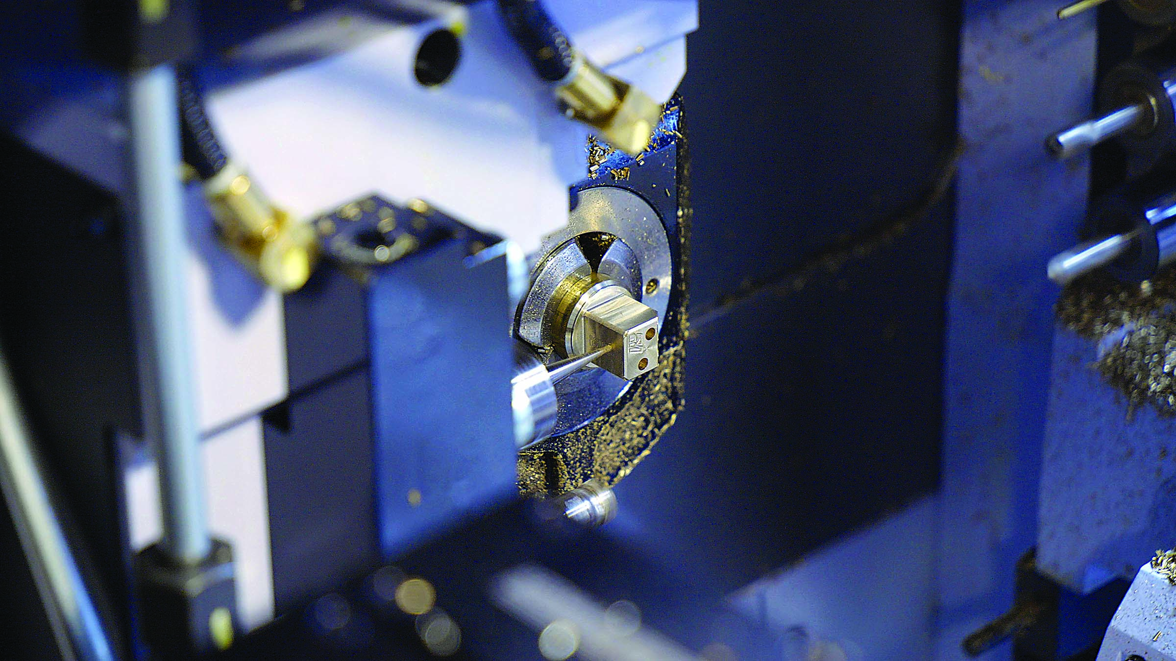
Courtesy of B. KennedyOn a Marubeni Citizen-Cincom K16 Swiss-style CNC lathe, a 0.047 "-dia. drill working from a slide servicing the subspindle creates a hole in a brass workpiece used to verify the setup for machining a dental abutment screw.Tactics and tools for Swiss-style machining.Swiss-style CNC lathes provide outstanding precision and flexibility while also posing special process control challenges and considerations.
Courtesy of B. Kennedy
On a Marubeni Citizen-Cincom K16 Swiss-style CNC lathe, a 0.047 “-dia. drill working from a slide servicing the subspindle creates a hole in a brass workpiece used to verify the setup for machining a dental abutment screw.
Tactics and tools for Swiss-style machining.
Swiss-style CNC lathes provide outstanding precision and flexibility while also posing special process control challenges and considerations. They offer machining capabilities and process control advantages apart from those of conventional CNC machines.
However, effectively operating a Swiss-style machine requires a different approach than machining on a conventional lathe. This article covers several key areas of Swiss operations, including segmentation, workpiece options, bushing maintenance, tooling, machine size and burr avoidance.
A Swiss-style machine differs from a standard lathe by virtue of a sliding headstock that feeds a rotating bar-fed workpiece through a guide bushing. Static and rotating side- and end-mounted tools cut within millimeters of the guide bushing, effectively eliminating workpiece overhang and part deflection. Multiple axes and driven tools perform nonturning operations, including milling, drilling and deburring. CNC technology enables standard tool geometries to produce complex and nonround shapes, and twin-spindle configurations facilitate finishing both ends of a part.
Swiss-style machines are categorized by their maximum bar capacity, typically from 2mm (0.08 “) to 38mm (1.50 “). Most smaller-capacity machines 16mm (0.63 “) in diameter and smaller can handle 1⁄16 “-dia. bars with minimal difficulty. In operation, Swiss-style machines can produce long runs of consistently precise, complex parts complete in one chucking. The machines routinely turn diameters down to 0.003 ” or smaller, and can machine features as small as 0.0003 “. Tight tolerances are the norm. A ±0.001 ” tolerance is considered wide open on a Swiss-style machine; shops running the machines typically work in four decimal places, and some shops consistently maintain tolerances of ±0.0002 “.
Part Segmentation
A Swiss-style machine’s sliding headstock and guide bushing provide superior workholding rigidity. To take full advantage of this inherent rigidity, the workpiece material must always remain in contact with the guide bushing. This requires the workpiece to be segmented—machined to completion one section at a time.
For example, all ID work is performed first. The material is fed through the guide bushing where a tool turns the part’s first diameter. Then the next feature, such as a groove or cross-hole, is machined. When the material advances through the guide bushing, the next feature, such as a diameter, is turned. This sequence continues through completion.
Segmentation assures that the workpiece is always supported by the guide bushing. As a result, rough and finish turning usually are not performed separately but in one pass. A rigid Swiss-style screw machine permits much heavier DOCs than a conventional lathe.
Material Significance
Workpiece material condition has a strong influence on the precision of parts produced on a Swiss-style machine. Most of all, the bar stock diameter must be consistent and typically is centerless-ground to a diametric tolerance of ±0.0002 “, particularly for exotic alloys. For example, titanium stock must be ground because it tends to be inconsistent and somewhat out of round.
Courtesy of B. Kennedy
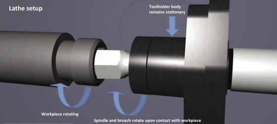
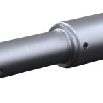
In a Swiss-style lathe, a sliding headstock feeds rotating stock through a guide bushing, eliminating overhang and deflection.
Courtesy of G. Crews
A key Swiss-style machining tactic is segmentation, in which the workpiece is closely supported by the guide bushing and machined to completion one section at a time.
But there is no requirement for more precision than necessary. Many material suppliers provide screw-machine-quality material that will handle perhaps 98 percent of a typical shop’s work without any difficulty. These higher-quality drawn materials generally have a tolerance of ±0.0005 “.
More important than absolute tolerances, however, is maintaining a consistent diameter along the entire length of the bar. A bar may be 0.0005 ” undersize, but as long as the entire bar is undersize by the same amount, adjustments can be made to produce the required part dimensions. In general, a Swiss-style machine can hold 60 percent of bar stock tolerance; that is, if bar stock varies by 0.001 “, the part can vary by as much as 0.0006 “.
Bar stock should be straight, exhibiting a bow of less than 0.001 ” per 12 ” of length. It also must be round. If the material is out of round, the machined part will be out of round, too.
That fact highlights a significant difference between Swiss-style and standard turning. On a conventional lathe, an out-of-round bar can be chucked between centers and turned until round. Conversely, in a Swiss-style machine, an out-of-round bar will be rotating in the guide bushing, and the machined part will be out-of-round as well.
Bushing Guidance
The configuration, adjustment and quality of the guide bushing are major factors in successful Swiss-style machining. An inaccurate or worn guide bushing often causes problems with dimensional control or tolerances.
The two most common styles of guide bushings are synchronous rotary and fixed. For parts with tolerances looser than ±0.0005 “, a rotary guide bushing is preferred. The rotary bushing and headstock rotate in sync with the workpiece material.
Courtesy of Marubeni Citizen-Cincom
This three-part bell was produced using three different Marubeni Citizen-Cincom Swiss-style machines. The handle was machined from 1 “-dia. stainless steel, the clapper turned from ½ “-dia. stainless, and the bell body was machined from 1¼ “-dia. brass.
Tighter-toleranced or smaller-diameter parts may require a fixed guide bushing, which remains static while the bar stock spins within it. A fixed guide bushing is adjustable and must be sized so the bar stock fully contacts the bushing but can still spin freely without seizing. The operator’s “feel” for the relationship between the bar and bushing helps determine a fixed guide bushing’s effectiveness. A good Swiss-style machine provides consistent repeatability, but if the bar stock, workholding or toolholding components are inconsistent, it doesn’t matter how accurately the machine can repeat.
Tooling Requirements
In Swiss-style machining it is essential to apply cutting tools engineered specifically for producing small parts, but until recently, these tools were difficult to find. Fortunately, a growing number of cutting tool manufacturers provide Swiss-style tools.
In general, turning tools for Swiss-style machines should have sharp edges, small nose radii and large clearance angles behind the cutting edge. Sharp tools minimize cutting forces. The greater the radius of the cutting edge, the more cutting force it generates, and the greater the possibility of workpiece deflection. Chipbreakers should be ground—not molded—into the cutting edge to ensure they cut and bend the chip effectively.
Courtesy of B. Kennedy
A carbide insert turns a brass workpiece, part of a 3½-minute process on a Marubeni Citizen-Cincom Swiss-style CNC lathe that involved 16 tools.
Clearance angles are an issue because Swiss-style tools operate in close proximity to the workpiece; sufficient clearance behind the cutting edge prevents it from rubbing on the workpiece. As part features shrink in size, tools with smaller nose radii are required.
Some tooling issues become less important as parts and machines grow in size. Clearance angles are not quite as critical. Tool settings need not be as precise—there is more margin for error, for example, in adjusting tool center height. Larger machines also offer more room to work.
Challenges in acquiring and caring for small tools also decrease when machining the contours of larger parts. Machining characteristics and toolholding requirements are dramatically different for a 0.025 “-dia. endmill compared to a ¼ “-dia. tool. You can push a ¼ “-dia. tool much harder than a 0.025 “-dia endmill.
Although toolmakers are expanding their offerings of Swiss-style tools, specials may still be needed for certain applications. For example, appropriate reamers were unavailable for a job requiring holes with a ±0.0003 ” finished tolerance. The solution was custom, tight-tolerance drills that achieved the finished hole tolerance without reaming.
A Machine that Fits
Review the print ads from this magazine to continue
This quick advertiser review unlocks the rest of the article and keeps the full-screen reader focused on the ads instead of the page chrome.
Continue reading
April 2011
QR codes and videos from this issue
Print QR codes, video callouts, and in-magazine links for this article now point to the CTE video hub in the HTML version.


MFGAxis Discussion