Courtesy of B. Kennedy
Operator Ricky Miller at the control panel of an ANCA RX-7 tool grinder at Siem Tool.
Tool and cutter grinder software continually evolves to expedite production of advanced cutting tools by toolmakers and machine shops.
The ability to use tools distinguishes humans from most other species. Certainly, the ability to apply complex, highly productive cutting tools distinguishes a shop from competitors further down the “evolutionary ladder.”
The manufacture of complex rotating tools generally takes place on CNC tool and cutter grinders. Regarding the process, Keith Grillot, regional sales manager for ANCA Inc., Wixom, Mich., said, “Tool grinding itself hasn’t changed for 100 years. If it is a manual grinder or CNC, you still have to approach the tool the same way.” However, appropriate software is needed to take advantage of the speed and accuracy of a CNC tool and cutter grinder.
Tool grinding is different than routine turning or milling. “If you look at grinding a cutting tool, you’re using a round wheel to cut on a round part and make flat surfaces,” Grillot said. “It’s a special art.” As a result, tool grinder CNCs and software have followed a separate evolutionary path from that of software that directs other metal-removal methods. “You go to a college and you see all kinds of CNC training, but there is really nothing for tool grinding,” he said.
While the idea of using a CNC machine might intimidate an operator accustomed only to manual tool grinding, an experienced manual operator usually can learn to use software easily because “he knows how the wheels have to approach the tool,” Grillot said. CNC software programs generally feature conversational interfaces. “They ask what’s the flute length and the relief angle, and the operator fills in the numbers,” he said.
According to Grillot, more shops are interested in grinding specials. “If you want to order a deviation from a catalog tooling item, it requires a long time frame [due to the exchange of drawings and files and the need for feedback],” he said, “but on the CNC it doesn’t matter. If you want a special flute length, for example, it’s just another number in the machine and off it goes.”
A shop may still buy tooling new, but will often modify it for a specific application. “You look where the tool is wearing, you make a couple of adjustments, and you have a special cutter just for your shop that provides a new advantage,” he said.
Grillot pointed out that industrywide efforts to reduce tooling inventories prompt shops to seek the ability to make replacement tools immediately, on-site. “As things start to pick back up, a lot of shops are looking to do in-house tool regrinding. For example, a lot of aerospace shops want to control their regrinding,” he said.
Adding Engineering Assistance
Many shops that previously focused exclusively on regrinding now are using CNC machines with advanced software to expand their capabilities, including production of specials, Grillot said, “so they can offer better service to their customers. In many cases, regrind shops are acting as tool engineers for manufacturing companies that have downsized their in-house tool engineering staffs.”
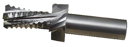
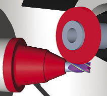
Courtesy of B. Kennedy
Advanced tool grinding software enabled Siem Tool to efficiently grind this tool to combine functions and replace multiple tools, reducing setups and costs.
One shop offering engineering services in addition to traditional toolmaking is Siem Tool Co., Latrobe, Pa. The company makes specialty form cutters, step tools and similar items. “We offer short lead times on complex tooling,” said Jim Gray, vice president of manufacturing. “We have standard product lines that get into some bigger volumes, but the majority is specialty tools.” The shop generally holds tolerances of 0.000 "/-0.002 " on tools such as endmills, which is “pretty standard in the industry,” Gray said. “But we do have some tools within a tenth, and some tighter.”
Gray said Siem Tool reviews the customer’s application to “see if we can improve the tool or combine multiple tools into one. Although it is simpler to build separate tools, when the customer is looking for cost savings we try to combine cutters.”
Siem Tool employs ANCA, Walter and Star tool grinders, running ANCA, Walter and Numroto software, respectively. “We have different machines and software because we do anything from standards to the most complex form cutters, and we have always updated our machines,” Gray said. “For some cutting tools, one machine makes us more competitive than another.”
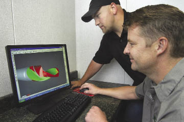
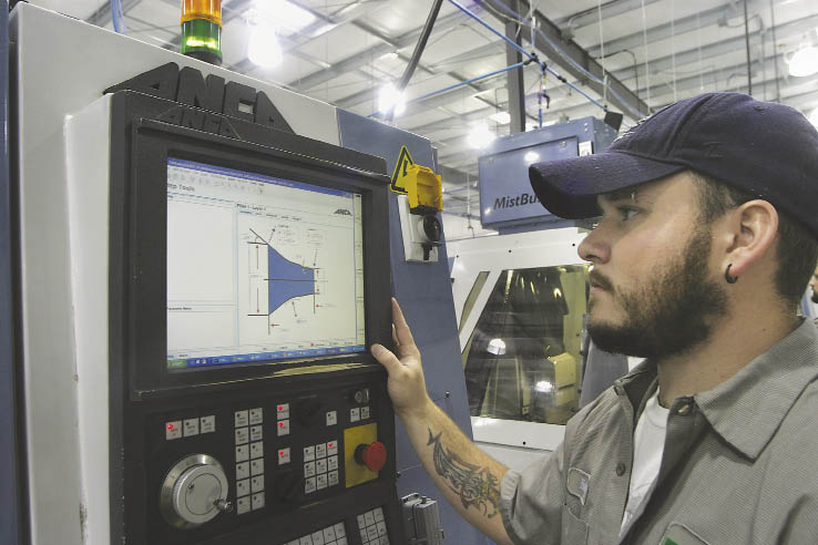
Courtesy of B. Kennedy
At specialty toolmaker Siem Tool, Sam Withrow (right), senior operator, and Jim Gray, vice president of manufacturing, view simulation of a tool grinding operation in iGrind software from ANCA.
Gray said tool grinding software evolves continually and “it has come a long way in the last 4 or 5 years.” He said the choice of a particular program is based on timing, as the tool and cutter grinder companies upgrade their machines and software and add capabilities. For example, recent upgrades to ANCA’s iGrind software allow operations that previously were performed in separate programs to be linked in one process. “You don’t have to go back and rework the tool in a different program,” Gray said.
Detailing that upgrade, ANCA President Russell Riddiford explained that grinding step features on a ballnose tool previously required a user “to grind the tool in the ballnose page, then come out of that page and go to a step-tool page to grind the step-tool portion.” Now, software utilizing a Windows-style interface eliminates the need to shift from one program to another. “You actually drag the programs together and build your own file. You can grind a ballnose into a step tool into a profile tool, all in the same program,” he said.
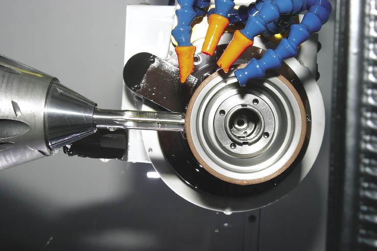
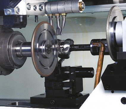
Courtesy of B. Kennedy
A grinding wheel poised at a reamer in an ANCA RX-7 tool grinder at Siem Tool.
Regarding the evolution of grinding software, Riddiford said it “is always developing, a work in progress.” As an example, he cited ANCA’s recent release of the RN30 Toolroom update for iGrind software. The update includes new features such as the AutoQ automatic wheel qualification process, which uses existing machine hardware to accurately ascertain wheel position at low cost, and an automatic white-sticking feature that provides untended, in-process cleaning of superabrasive wheels, which enhances the ability to grind tools unattended.
Simulated Benefits
All of the tool grinding software packages used at Siem Tool simulate the grinding process in 3-D computer model form before grinding an actual tool. Simulation speeds the shop’s throughput by enabling operators to write and test new programs offline while programs created earlier are running. “All of our operators do their own programming, and we reduce downtime by having them go in and simulate their products offline,” Gray said.
Simulation is also a key element of the shop’s custom tool engineering effort. Tool features are based on Siem Tool’s application experience. “We know how our tool geometries will adapt to cutting a certain material,” Gray said. For complex, multiple-element tools, he drafts an initial design. “Then I’ll review it with a senior guy. Next, we start doing the simulation, and we can see what our problems are.” The simulation usually is performed before the final quoting of the tool. “That’s when we figure out what machine we are going to grind it on, what works best, and where we can get a reduction in cost, setup times and run times,” Gray said.
Facilitating Complexity
As end users demand more complex tool geometries, developers of tool grinding software respond with more capable programs. According to Eric Schwarzenbach, president of Rollomatic Inc., Mundelein, Ill., tools with variable helixes and variable flute spacing “are becoming very common to reduce the harmonics in milling.” The uneven spacing prevents development of repetitive vibration that can cause chatter or even break a tool. Variations in flute spacing can be a matter of a few degrees. To create tool grinding programs for these geometries, Rollomatic developed a software platform called VirtualGrind Pro.
Schwarzenbach said the software enables the geometries to be ground in a single pass. “In the past, when you had a different flute spacing, you had to take two cuts per flute to make it different from tooth to tooth.” Performing the process in a single pass reduces grinding time and improves tool cosmetics and performance. When two passes were required to create a flute contour, “you had a blend in the flute, a little step or mark. When you have one pass, the tool looks better and performs better too,” Schwarzenbach said. While a step or blend mark can impede chip flow, producing the contour in a single pass results in a smooth ground surface that promotes chip evacuation, he said.
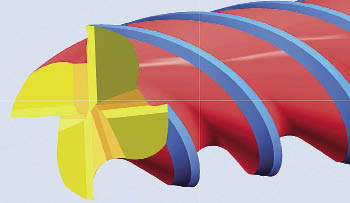
Courtesy of Rollomatic
Variable helixes and flute spacing are employed to reduce harmonics in milling, and uneven spacing prevents development of repetitive vibration that can cause chatter or even break a tool. This variable-helix tool model was created in the VirtualGrind Pro software platform from Rollomatic.
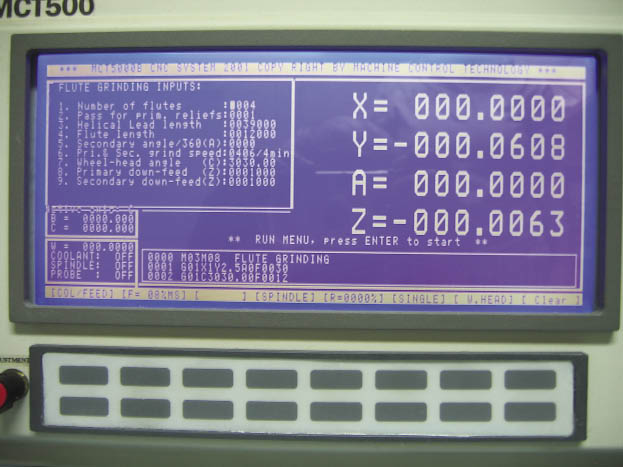
Courtesy of Machine Control Technology
Tool grinding software on Machine Control Technology grinders is comprised of macro programs that shops can use as building blocks, linking them to generate a complete grinding program to produce a unique tool configuration.
Another advantage is that the software enables users to regrind the tools when worn. “In the past, regrinding was pretty simple, but with different indexes and different helixes, regrinding is becoming more complex,” Schwarzenbach said.
Many tool grinding software packages feature modularity that permits a shop to assemble separate elements and create specialized tool grinding programs. Machine Control Technology, Buena Park, Calif., produces custom CNC grinding machines for specific applications and standard machines. The company’s MCT500 and MCT5000 series CNC tool and cutter grinders have built-in macro programs for endmills, reamers, countersinks, step drills, step OD drills and engraving tools. Company Owner Sam Yu said a shop can use those macro programs as building blocks and link them to generate a complete grinding program to produce a unique tool configuration. In addition, an edit mode enables users to modify the programs and further fine-tune the process to produce specific tool features.
Simulation and Grinding
Another advance in software is integration of the grinding and simulation programs, a feature of the Helitronic Tool Studio software for Walter tool and cutter grinders, produced by United Grinding, Fredericksburg, Va. “You are not designing your part in one program and then simulating it in a separate software package and going back and forth,” said Ed Sinkora, marketing manager for United Grinding’s tool division. “It’s a seamless whole.” Because the simulation models the machine, workholding, wheel and part, collision detection is integrated. The machine will not grind the tool if the simulation shows a collision is imminent.
Rick Martin, vice president of United Grinding’s tool division, said the Helitronic Tool Studio software also integrates CNC measurement of the grinding wheel. “This way, the model matches the real world almost exactly, and setup time on the machine is minimal,” he said. Martin added that integrating CNC measuring, simulation and grinding is also crucial in the production of microtools. “The smaller the tool, the more damaging any inaccuracy will be, so 3-D modeling must be near perfect to be useful,” he said.
Walter’s Helitronic Micro tool grinding machine uses the software to produce tools in diameters from 0.020 " to 0.50 ", and grinds smaller and larger tools as well.
Courtesy of United Grinding
Helitronic Tool Studio software for Walter tool and cutter grinders integrates grinding and simulation programs. The company says modeling of the machine, workholding, wheel and part optimizes collision detection, and the machine will not grind the tool if simulation shows a collision is imminent. This screen image marks components that will collide in red.
Integration of simulation and grinding programs also provides in-process advantages. During grinding operations, the Helitronic Tool Studio simulation allows the operator “to see where machine is, where the wheel is located and how it is approaching the tool,” said Mike Hilbert, tool design and production engineer at Professional Tool Grinding Inc., South Easton, Mass. “Even if the coolant is shooting all over the machine, he can still see what is going on.” Operators can make adjustments to the grinding process as the machine is running parts.
Professional Tool Grinding concentrates on manufacturing specials. In most cases, the shop works from customers’ part prints, but in some situations will engineer a custom tool and provide variations on the basic design. “We have to find a tool that’s going to work with their machining operations, how fast they are running and what type of coolant they are using,” Hilbert said. “We might make them four different versions of the tool with different geometries. They may set their job up and tell us that revision B is working better than revision A. Then we make a run of revision B for them.” To create incremental variations of a tool geometry, the shop just inputs different numbers into the grinding program.
User Adjustable
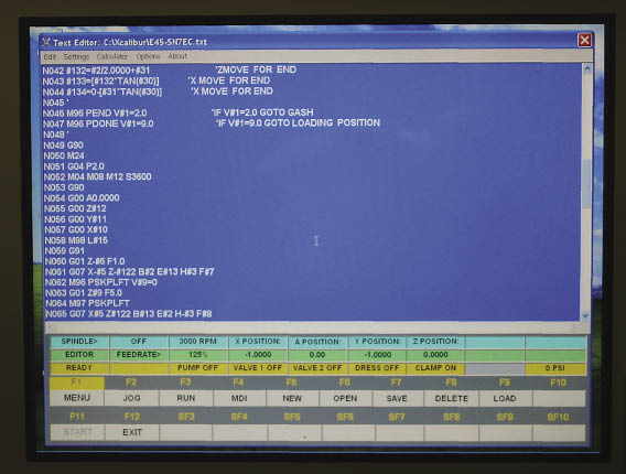
Advanced tool grinding software allows users to fine-tune their manufacturing process. Dan Wayman, president of CNC tool grinder supplier Excalibur Tool Inc., Murphy, Ore., said the software interface on the company’s machines is written in-house. It converts G code into language the machine’s Douloi Automation controls can understand, and employs the company’s “G-code plus” software, which is capable of complex math statements, jumps, loops and data collection, according to Wayman.
Although standard G code forms the basis for Excalibur Tool’s grinding programs, “very few of our customers actually sit down and write a program,” he said. “Probably 98 percent of the folks just run the G code programs that we give them. They buy a machine and are going to make endmills, and we have endmill programs that are already written. The operator can enter parameters for the diameter of the tool, the length of cut and for every variable needed to grind the part.”
Courtesy of Excalibur Tool
Excalibur Tool says the software interface for its tool grinding machines is written in-house and employs the company’s own “G-code plus” that is capable of complex math statements, jumps, loops and data collection.
However, he said, because G code can be edited, users can “tweak” a program to rearrange steps or make other changes. “We’ll send them an endmill program; if they want it to go in a certain order, they can copy and paste it and do whatever they want with it.” Such flexibility, he said, can be challenging. “It is easy to use because you can program anything you can imagine. On the other hand, it is hard to use because you can program anything you can imagine … you have to know what you want.”
Wayman said he sees a new group of customers becoming interested in CNC tool and cutter grinding technology. “We have some big companies that use our machines, but it seems like in the last 5 to 6 years we are into a new group of customers that were hand-grind shops for years. They buy their first E45 CNC grinder from us and discover all the things they can do with it. Then, as they get more work, they buy a 6-axis RoboGrind robot-loaded machine to handle the new workload. I’m starting to get a lot of the smaller guys stepping in.”
The combination of more-sophisticated tool grinding machines with continually updated software is enabling those “smaller guys” to move up in the evolutionary hierarchy of toolmaking competitiveness. CTE
Courtesy of United Grinding
The combination of CNC and CAD/CAM technologies with Walter’s 5-axis Helitronic Tool Studio software transforms the tool grinder into a combined part grinder and basic machining center. Walter has initially aimed the package at the manufacture of orthopedic components, such as the artificial knee shown here.
Beyond tools and cutters
The CNC technology and software used in most tool and cutter grinders have evolved in parallel. Walter, for example, for many years utilized controls from German control maker Andron GmbH, and the control and software were developed and improved in unison. However, as part of long-term product development, the company decided to adopt the widely applied Fanuc control, according to Ed Sinkora of United Grinding, which produces Walter and other grinder brands. Following a development period to maximize the compatibility of the control and tool grinding software, users now can grind complex tool geometries using the Helitronic Tool Studio software on Walter grinders with Fanuc controls.
Adoption of the commonly used Fanuc control technology has expanded production capabilities. Walter created an interface and post-processor that enables its software and machines to work with files created in Siemens PLM NX (formerly known as Unigraphics), a CAD/CAM package. The interface permits 3-D simulation and grinding not only of cutting tools, but of any part that has been defined in PLM NX or another CAD/CAM package for which there is a post-processor matched to the Fanuc control.
Because the PLM NX post-processor is not designed for a specific application, operations other than grinding are possible, Sinkora said. A grinding machine’s wheel changer can also be used as a toolchanger to hold drills, taps and endmills. The combination of CNC and CAD/CAM technologies with Walter’s 5-axis Helitronic Tool Studio software essentially transforms the tool grinder into a combined part grinder and basic machining center, able to produce complex, ground contours as well as milled surfaces and drilled and tapped mounting holes. Walter has initially aimed the package at the manufacture of orthopedic components, such as artificial knees.
—B. Kennedy
Contributors
ANCA Inc.
(248) 926-4466
www.anca.com
Excalibur Tool Inc.
(541) 862-2939
www.excalibur-tool.com
Machine Control Technology
(714) 952-4622
www.machinecontrol technology.com
Professional Tool Grinding Inc.
(508) 230-3535
www.ptgspecials.com
Rollomatic Inc.
(866) 713-6398
www.rollomaticusa.com
Siem Tool Co.
(724) 520-1904
www.siemtool.com
United Grinding
(540) 898-3700
www.grinding.com
Related Glossary Terms
- 3-D
3-D
Way of displaying real-world objects in a natural way by showing depth, height and width. This system uses the X, Y and Z axes.
- chatter
chatter
Condition of vibration involving the machine, workpiece and cutting tool. Once this condition arises, it is often self-sustaining until the problem is corrected. Chatter can be identified when lines or grooves appear at regular intervals in the workpiece. These lines or grooves are caused by the teeth of the cutter as they vibrate in and out of the workpiece and their spacing depends on the frequency of vibration.
- computer numerical control ( CNC)
computer numerical control ( CNC)
Microprocessor-based controller dedicated to a machine tool that permits the creation or modification of parts. Programmed numerical control activates the machine’s servos and spindle drives and controls the various machining operations. See DNC, direct numerical control; NC, numerical control.
- concentrates
concentrates
Agents and additives that, when added to water, create a cutting fluid. See cutting fluid.
- coolant
coolant
Fluid that reduces temperature buildup at the tool/workpiece interface during machining. Normally takes the form of a liquid such as soluble or chemical mixtures (semisynthetic, synthetic) but can be pressurized air or other gas. Because of water’s ability to absorb great quantities of heat, it is widely used as a coolant and vehicle for various cutting compounds, with the water-to-compound ratio varying with the machining task. See cutting fluid; semisynthetic cutting fluid; soluble-oil cutting fluid; synthetic cutting fluid.
- endmill
endmill
Milling cutter held by its shank that cuts on its periphery and, if so configured, on its free end. Takes a variety of shapes (single- and double-end, roughing, ballnose and cup-end) and sizes (stub, medium, long and extra-long). Also comes with differing numbers of flutes.
- flat ( screw flat)
flat ( screw flat)
Flat surface machined into the shank of a cutting tool for enhanced holding of the tool.
- gang cutting ( milling)
gang cutting ( milling)
Machining with several cutters mounted on a single arbor, generally for simultaneous cutting.
- grinding
grinding
Machining operation in which material is removed from the workpiece by a powered abrasive wheel, stone, belt, paste, sheet, compound, slurry, etc. Takes various forms: surface grinding (creates flat and/or squared surfaces); cylindrical grinding (for external cylindrical and tapered shapes, fillets, undercuts, etc.); centerless grinding; chamfering; thread and form grinding; tool and cutter grinding; offhand grinding; lapping and polishing (grinding with extremely fine grits to create ultrasmooth surfaces); honing; and disc grinding.
- grinding machine
grinding machine
Powers a grinding wheel or other abrasive tool for the purpose of removing metal and finishing workpieces to close tolerances. Provides smooth, square, parallel and accurate workpiece surfaces. When ultrasmooth surfaces and finishes on the order of microns are required, lapping and honing machines (precision grinders that run abrasives with extremely fine, uniform grits) are used. In its “finishing” role, the grinder is perhaps the most widely used machine tool. Various styles are available: bench and pedestal grinders for sharpening lathe bits and drills; surface grinders for producing square, parallel, smooth and accurate parts; cylindrical and centerless grinders; center-hole grinders; form grinders; facemill and endmill grinders; gear-cutting grinders; jig grinders; abrasive belt (backstand, swing-frame, belt-roll) grinders; tool and cutter grinders for sharpening and resharpening cutting tools; carbide grinders; hand-held die grinders; and abrasive cutoff saws.
- grinding wheel
grinding wheel
Wheel formed from abrasive material mixed in a suitable matrix. Takes a variety of shapes but falls into two basic categories: one that cuts on its periphery, as in reciprocating grinding, and one that cuts on its side or face, as in tool and cutter grinding.
- machining center
machining center
CNC machine tool capable of drilling, reaming, tapping, milling and boring. Normally comes with an automatic toolchanger. See automatic toolchanger.
- milling
milling
Machining operation in which metal or other material is removed by applying power to a rotating cutter. In vertical milling, the cutting tool is mounted vertically on the spindle. In horizontal milling, the cutting tool is mounted horizontally, either directly on the spindle or on an arbor. Horizontal milling is further broken down into conventional milling, where the cutter rotates opposite the direction of feed, or “up” into the workpiece; and climb milling, where the cutter rotates in the direction of feed, or “down” into the workpiece. Milling operations include plane or surface milling, endmilling, facemilling, angle milling, form milling and profiling.
- outer diameter ( OD)
outer diameter ( OD)
Dimension that defines the exterior diameter of a cylindrical or round part. See ID, inner diameter.
- parallel
parallel
Strip or block of precision-ground stock used to elevate a workpiece, while keeping it parallel to the worktable, to prevent cutter/table contact.
- payload ( workload)
payload ( workload)
Maximum load that the robot can handle safely.
- reamer
reamer
Rotating cutting tool used to enlarge a drilled hole to size. Normally removes only a small amount of stock. The workpiece supports the multiple-edge cutting tool. Also for contouring an existing hole.
- relief
relief
Space provided behind the cutting edges to prevent rubbing. Sometimes called primary relief. Secondary relief provides additional space behind primary relief. Relief on end teeth is axial relief; relief on side teeth is peripheral relief.
- toolchanger
toolchanger
Carriage or drum attached to a machining center that holds tools until needed; when a tool is needed, the toolchanger inserts the tool into the machine spindle. See automatic toolchanger.
- turning
turning
Workpiece is held in a chuck, mounted on a face plate or secured between centers and rotated while a cutting tool, normally a single-point tool, is fed into it along its periphery or across its end or face. Takes the form of straight turning (cutting along the periphery of the workpiece); taper turning (creating a taper); step turning (turning different-size diameters on the same work); chamfering (beveling an edge or shoulder); facing (cutting on an end); turning threads (usually external but can be internal); roughing (high-volume metal removal); and finishing (final light cuts). Performed on lathes, turning centers, chucking machines, automatic screw machines and similar machines.
 ARTICLES