The science of milling sounds

Author Dr. Scott Smith
Published
February 01, 2013 - 10:30am

Milling sounds range from loud to quiet, and experienced machinists often use those sounds to judge what is occurring in the cutting zone. It is difficult to position a sensor such as an accelerometer or a displacement probe close to the cutting zone, and it is often a challenge to see the cutting zone, but the sounds are pervasive.

Some of the sounds are normal—and expected—and some indicate trouble, but how can you tell which are which? The sounds are often sorted by their frequency, or pitch. Sound can be measured using a microphone and sorted into frequencies using a Fourier analyzer. This device takes a time-varying sound signal as an input and outputs a graph that shows the composition of the sound as a number of frequencies with different intensities.

Figure1.tif
Courtesy of All images: Manufacturing Laboratories Inc.

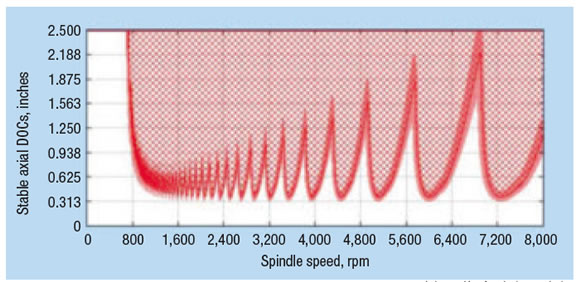
Figure 1. The red hatched area in this stability lobe diagram indicates chatter, and the white area indicates stable machining.

8947.png

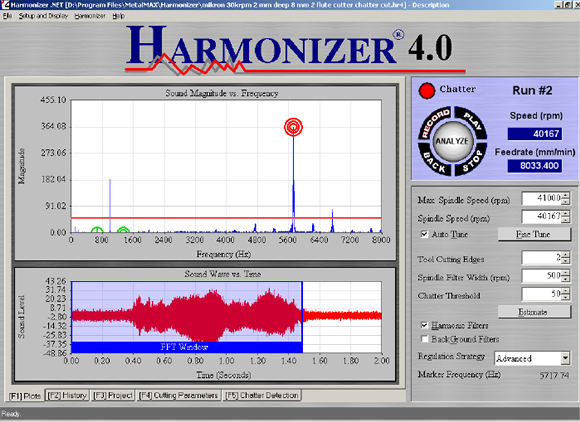
Figure 2. The red bull’s eye in the Harmonizer chatter control product, which detects chatter using the sound signal measured with a microphone, indicates the presence of chatter at a frequency slightly higher than 5,600 Hz when cutting with a 2-flute, 8mm-dia. tool. The top part of the figure shows sound magnitude (loudness) vs. frequency. The horizontal red line is a threshold, so that background noise does not trigger the system. The bottom part of the figure shows the sound signal vs. time, and the box surrounds the sound of the cut. The software is partway through an optimization process, and the most recent cut was at 40,167 rpm. The check in the harmonic filters checkbox indicates the “normal sounds” have been removed from this picture.

Normal situations include:

1. The sound of tool teeth hitting the workpiece. These impacts cause forces that make the cutting tool and workpiece vibrate, which produces the sound. The tooth-impact frequency is given by ft = n × m ÷ 60, where n is the spindle speed in rpm, m is the number of teeth on the tool and ft is the tooth-impact frequency in cycles per second, or Hz. For example, if the tool has two teeth and the spindle speed is 13,200 rpm, the tooth impact frequency is 440 Hz, which, for the musically inclined, is the note A above middle C.

2. Integer multiples of the tooth-impact frequency. Because the cutting force is not purely sinusoidal, there are frequency components that are exact integer multiples of the tooth-impact frequency (2 × 440 = 880 Hz, 3 × 440 = 1,320 Hz and so on for the previous example). These integer multiples of the tooth-impact frequency are called “harmonics,” and, because they are directly related to the tooth-impact frequency, the sound produced is very pure and “clean,” like a single note.

3. Runout frequencies and harmonics. Because the cutting tool is not exactly centered in the spindle and the teeth are not exactly the same, there is also a sound produced at a frequency once per revolution and integer multiples of that frequency. For the previous example, the runout frequency would be 220 Hz.

A major characteristic of these normal sounds is that they change linearly with the spindle speed, because they are all forced vibrations directly driven by the rotating spindle.

Chatter is the main sound that indicates trouble. Chatter is a different kind of vibration, called a self-excited vibration. If the cutting tool vibrates as a tooth passes through the workpiece, the tooth imparts a wavy surface. The next tooth encounters the wavy surface, which generates a variable force, and causes more vibration. Chatter happens at frequencies near and a little above the natural frequencies of the machine-tool-and-workpiece system.

Whether or not chatter occurs for a particular combination of machine, cutting tool and workpiece strongly depends on the spindle speed and axial and radial DOC. The map of stable and chatter conditions is called a stability lobe diagram (Figure 1).

Chatter is often loud and sometimes scary for machinists because it can lead to workpiece damage and broken tools. So, it would be helpful to automatically detect chatter, and the frequency of the sound provides a way. The chatter frequency is not linearly proportional to the tooth impact frequency or runout. The sound it makes is not “pure” and often is harsh or raspy.

Figure 2 shows the sound measured during a chattering cut. The lower part of the figure shows the time-varying microphone signal, and the cutting sound is contained in the blue window. The upper part of the figure shows the loudness of the frequencies contained in the sound signal (the output of the Fourier analyzer). The software used to make this measurement flags loud sounds that are not in the normal group as chatter. In this case, a red bull’s eye marks chatter, with a frequency slightly higher than 5,600 Hz.

The pervasiveness of the cutting sound is useful, as is the clear distinction between normal and chatter sounds. The sound of milling is easy and inexpensive to measure, and measurement provides a quick and simple way to detect chatter during the cut. CTE

About the Author: Dr. Scott Smith is a professor and chair of the Department of Mechanical Engineering at the William States Lee College of Engineering, University of North Carolina at Charlotte, specializing in machine tool structural dynamics. Contact him via e-mail at kssmith@uncc.edu.

Related Glossary Terms

  • chatter

    chatter

    Condition of vibration involving the machine, workpiece and cutting tool. Once this condition arises, it is often self-sustaining until the problem is corrected. Chatter can be identified when lines or grooves appear at regular intervals in the workpiece. These lines or grooves are caused by the teeth of the cutter as they vibrate in and out of the workpiece and their spacing depends on the frequency of vibration.

  • cutting force

    cutting force

    Engagement of a tool’s cutting edge with a workpiece generates a cutting force. Such a cutting force combines tangential, feed and radial forces, which can be measured by a dynamometer. Of the three cutting force components, tangential force is the greatest. Tangential force generates torque and accounts for more than 95 percent of the machining power. See dynamometer.

  • gang cutting ( milling)

    gang cutting ( milling)

    Machining with several cutters mounted on a single arbor, generally for simultaneous cutting.

  • milling

    milling

    Machining operation in which metal or other material is removed by applying power to a rotating cutter. In vertical milling, the cutting tool is mounted vertically on the spindle. In horizontal milling, the cutting tool is mounted horizontally, either directly on the spindle or on an arbor. Horizontal milling is further broken down into conventional milling, where the cutter rotates opposite the direction of feed, or “up” into the workpiece; and climb milling, where the cutter rotates in the direction of feed, or “down” into the workpiece. Milling operations include plane or surface milling, endmilling, facemilling, angle milling, form milling and profiling.

  • pitch

    pitch

    1. On a saw blade, the number of teeth per inch. 2. In threading, the number of threads per inch.

Author

Dr. Scott Smith is a professor and chair of the Department of Mechanical Engineering at the William States Lee College of Engineering, University of North Carolina at Charlotte, specializing in machine tool structural dynamics. Contact him via e-mail at kssmith@uncc.edu.

Click on the author to view all of their articles!