Riding herd on runout

Author Cutting Tool Engineering
Published
July 01, 2010 - 11:00am

Mega_E_Action.tif

Courtesy of All images: BIG Kaiser

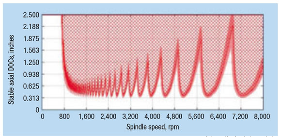
Toolholders with increased taper-to-taper contact, such as this Mega E collet chuck from BIG Daishowa, are useful for high-speed milling since they enable stable cutting. 

Many machine shops lack objective criteria for making toolholder purchasing decisions. They say every tooling manufacturer claims high accuracy, perfect balance and large clamping forces. With so many choices and little to distinguish one toolholder from the next, most purchasing decisions are made by price alone.

However, using this criteria overlooks the critical effect that runout has on machining accuracy and tool life. Many machine shops and parts manufacturers are not aware they can improve runout significantly by using the right toolholders. 

Figure1.ai

Work material1055 steelSpeed, carbide250 sfmSpeed, HSS90 sfmFeed0.004 iprHole depth, 3xD0.47 "Hole depth, 5xD0.60 "Drill diameter0.118 " (3mm)

Figure 1: Effect of runout on holemaking productivity (left). Test specifications (right).

Two important variables in determining acceptable runout are tool size and composition. With tools 3⁄4 " in diameter or larger, runout of 0.0005 " may not impair performance and tool life. However, with smaller tools runout may need to be much better than 0.0005 ". 

Tool materials are also critical. For example, solid-carbide drills can last much longer than HSS drills—but only if runout is tightly controlled. 

Our company conducted an informal customer survey by asking, “What is good runout?” The consensus was that good runout is 0.0005 ". We decided to evaluate this benchmark using tests of various cutting tools. Figure 1 shows data from drilling tests performed at the BIG Daishowa Mega Technical Center in Awaji, Japan. Each drill was tested under the same conditions, with only runout changed for each value. 

Figure2.ai

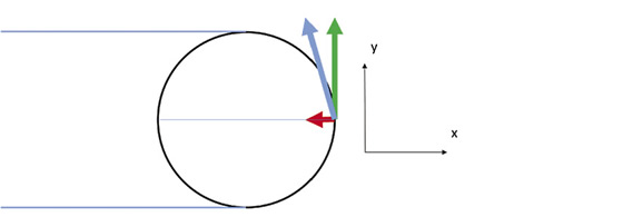
Figure 2: Effect of runout on average combined tool life for carbide and HSS tools tested.

A 3mm-dia., solid-carbide drill with 0.00008 " of runout produced 148 holes at 3 times diameter until the primary cutting edge experienced 0.008 " of wear, at which point tool life was considered to be over. A second 3mm-dia. carbide drill with 0.0002 " of runout under the same conditions produced just 125 holes using the same tool life measurement. The test was repeated two more times with runouts of 0.0004 " and 0.0006 ", with a decrease in tool life as runout increased.

The next test used the same four runout values for a 3mm-dia. HSS drill at 3 times diameter. A third test mirrored the first two, but used a 3mm.-dia. HSS drill at 5 times diameter, with through- the-tool coolant. 

To summarize the results:

 Carbide has the highest sensitivity to diminished tool life due to runout. Improving runout from 0.0006 " to 0.00008 " tripled tool life of the solid-carbide drill. Keep in mind that tool users in our survey considered 0.0005 " runout to be acceptable on average.

 HSS tools were slightly less sensitive than their solid-carbide counterparts to diminished life. Improving runout from 0.0006 " to 0.00008 " produced a 230 percent improvement in tool life. Through-coolant HSS tools were even less sensitive to diminished tool life, producing only a 160 percent improvement in tool life. 

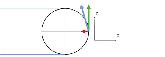
If a drill does not run concentric to its centerline, higher forces are generated in the radial direction of the highest margin, causing more wear on one side.

This data was used to plot tool life efficiency based on average results for both carbide and HSS tools. From this data, tool life efficiency can be plotted based on runout, whereby theoretical “0” runout is equal to 100 percent tool life expectancy (Figure 2). At the “acceptable average” runout of 0.0005 ", tool life is cut in half.

Figure3.ai

Work material1055 steelCutting speed300 sfmSpindle speed (rpm)2,900Feed rate0.004 "/fluteFeed46.4 ipmAxial depth0.60 "Radial step0.004 "

Figure 3: Effect of runout on a 4-flute, 10mm-dia. carbide endmill (top). Test specifications (directly above). 

Figure4.ai

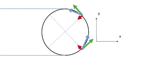
Figure 4: Maximum runout based on tool diameter and chip load.

Many shops use toolholders, such as 3-jaw drill chucks, that allow drill runout to exceed 0.001 ". Extrapolating from our test data, a solid-carbide drill with runout of 0.001 " would produce fewer than 25 holes. A higher-quality chuck, though more expensive, could improve tool life dramatically.

Savings can be measured in cost per hole. An average price for the 3mm-dia. carbide drills used in our test is $40. With runout of 0.00008 ", this drill can produce 148 holes, or $0.27 per hole. With runout of 0.0006 ", the cost per hole nearly triples to $0.80 per hole. As a result, manufacturers willing to accept 0.0006 " runout are passing up an opportunity to cut drilling costs by 66 percent.

BIG Daishowa ran similar tests to calculate values for a 4-flute, 10mm-dia. carbide endmill (Figure 3 on page 62). Cutting length increased from 528 ' to 693 ', 1.3 times longer, as runout decreased from 0.0006 " to 0.00008 ". The reason is clear: With runout of only 0.00008 ", the cutting forces are evenly distributed on each flute, whereas with runout of 0.0006 ", an excessive force will be applied to only one flute. Less runout helps stabilize the cutting depth on each flute and produces a finer surface finish.

Allowable TIR should be based on different values for tools of different diameters. Figure 4 shows the constant relationship between tool diameter and runout as a function of chip load. The data is based on 0.0005 " TIR as a starting point for a ½ "-dia. tool, from which the allowable TIR can be calculated for smaller tools and their respective chip loads. For example, if a 1⁄16 " endmill with three flutes is profiling mold steel, the effective chip load is 0.0002 ipt, which means the tool will be unbalanced when runout is 0.0005 ".

Gage bar testing runout.tif

Regular inspection with gage bars helps identify potential spindle problems, and can reduce downtime and spindle repairs.

Even the best collet chuck cannot deliver superior performance in an old or worn spindle. Shops should check their spindles regularly for runout using a precision gage bar. One popular gage is a simple straight bar used by slowly rotating the spindle and measuring runout with an indicator. 

Dynamic runout gages are useful for high-speed machining. When the spindle is rotated at low speeds, centrifugal forces have little or no influence on runout. However, as the spindle speeds increase, centrifugal forces increase exponentially and can cause extreme runout.

A dynamic runout gage typically has a precise point for accurate measurement of laser alignment tools in the X and Y axes. Recent tests by BIG Daishowa of high-speed spindles showed that many machines, while accurate at 500 rpm, had runout exceeding 0.001 " at 30,000 rpm.

Other influences on runout include taper-to-taper contact, and the angle of the collet and corresponding clamping range. (see sidebar on page 60).

What many shops believe is acceptable runout is actually unacceptable if the shop wants to improve tool life. A manufacturer basing toolholder purchase decisions solely on the price of the toolholder may end up choosing a more expensive alternative, based on tool life and cost per hole, while sacrificing quality and accuracy. CTE

About the author: Jack Burley is vice president of sales and engineering for BIG Kaiser Precision Tooling Inc., Hoffman Estates, Ill. He has more than 25 years of experience in metalworking and has been with BIG Kaiser since the founding of its U.S. operations in 1990. Contact him at (847) 228-7660, ext. 111, or by e-mail at jburley@bigkaiser.com. For more information about the company’s products, enter #350 on the I.S. Form.

Moldmaker handles runout with new collet 

Controlling runout sometimes requires a change of toolholders. For example, Ideal Tool Co., Meadville, Pa., was hard milling a 14 "×8 "×1¾ " stamping die from S7 tool steel. Runout had been from 0.001 " to 0.0015 ". After the company began using a BIG Daishowa HSK-A63 Mega New Baby collet chuck, runout dropped to less than 0.0005 ".

Ideal Tool uses a Makino V55 with HSK-A63 spindle at speeds up to 20,000 rpm and feeds to 150 ipm. Like most mold shops, it runs many limited production jobs and makes numerous tooling changes. Using the new chuck, changeouts that had taken 5 to 10 minutes are completed in 30 seconds. Because the company changes out upwards of 10 chucks per job, the impact on productivity was immediate. 

—J. Burley


Mega_N_Action.tif

This BIG Mega New Baby collet chuck has a 12º collet angle, which provides better runout control and clamping force than higher-angle chucks.

Collet features that can control runout 

Shops wishing to control runout should take a close look at toolholder features such as taper-to-taper contact, as well as collet angles and corresponding clamping ranges.

In a typical collet chuck system, the collet angle is 16º, which offers a clamping range of 0.039 ". However, the tradeoff to having this range is less runout control and less clamping force. For example, BIG Mega New Baby collet chucks have a 12º angle, giving them only a 0.020 " clamping range but considerably better runout control and clamping force than higher-angle chucks, according to the company. Another product, the BIG Mega E collet chuck, is for holding endmills and has an angle of just 8º, giving it even higher clamping force, rigidity and runout control.

The BIG Mega Micro collet chuck, for holding micro cutting tools, also has a shallow taper collet angle. These collets are available in increments of 0.004 " on diameter to control runout.

More concentric clamping and increased clamping force can also improve runout. For example, BIG Daishowa’s Mega ER Grip AA-grade collet chuck system is available in 2mm to 3mm diameters in 0.1mm-dia. increments, 3mm to 6mm diameters in 0.25mm-dia. increments and 6mm to 20mm diameters in 0.5mm-dia. increments. A smaller range provides a more concentric clamping of the tool shank, according to BIG Daishowa.

The Mega ER Grip body has an increased contact length of the internal taper, which reduces collet overhang, and a smaller clamping range than similar products. These features improve rigidity, clamping force and runout accuracy, according to the company. The chuck system also has a prebalanced body with tapped holes around the periphery for precision balancing with screws and offers only dual-contact interfaces.

BIG Daishowa guarantees runout of all its collets of no greater than 0.00012 " (3µm) at four times tool diameter and 0.00004 " at the nose. 

—CTE Staff

Related Glossary Terms

  • chuck

    chuck

    Workholding device that affixes to a mill, lathe or drill-press spindle. It holds a tool or workpiece by one end, allowing it to be rotated. May also be fitted to the machine table to hold a workpiece. Two or more adjustable jaws actually hold the tool or part. May be actuated manually, pneumatically, hydraulically or electrically. See collet.

  • collet

    collet

    Flexible-sided device that secures a tool or workpiece. Similar in function to a chuck, but can accommodate only a narrow size range. Typically provides greater gripping force and precision than a chuck. See chuck.

  • coolant

    coolant

    Fluid that reduces temperature buildup at the tool/workpiece interface during machining. Normally takes the form of a liquid such as soluble or chemical mixtures (semisynthetic, synthetic) but can be pressurized air or other gas. Because of water’s ability to absorb great quantities of heat, it is widely used as a coolant and vehicle for various cutting compounds, with the water-to-compound ratio varying with the machining task. See cutting fluid; semisynthetic cutting fluid; soluble-oil cutting fluid; synthetic cutting fluid.

  • endmill

    endmill

    Milling cutter held by its shank that cuts on its periphery and, if so configured, on its free end. Takes a variety of shapes (single- and double-end, roughing, ballnose and cup-end) and sizes (stub, medium, long and extra-long). Also comes with differing numbers of flutes.

  • flutes

    flutes

    Grooves and spaces in the body of a tool that permit chip removal from, and cutting-fluid application to, the point of cut.

  • gang cutting ( milling)

    gang cutting ( milling)

    Machining with several cutters mounted on a single arbor, generally for simultaneous cutting.

  • high-speed steels ( HSS)

    high-speed steels ( HSS)

    Available in two major types: tungsten high-speed steels (designated by letter T having tungsten as the principal alloying element) and molybdenum high-speed steels (designated by letter M having molybdenum as the principal alloying element). The type T high-speed steels containing cobalt have higher wear resistance and greater red (hot) hardness, withstanding cutting temperature up to 1,100º F (590º C). The type T steels are used to fabricate metalcutting tools (milling cutters, drills, reamers and taps), woodworking tools, various types of punches and dies, ball and roller bearings. The type M steels are used for cutting tools and various types of dies.

  • inches per minute ( ipm)

    inches per minute ( ipm)

    Value that refers to how far the workpiece or cutter advances linearly in 1 minute, defined as: ipm = ipt 5 number of effective teeth 5 rpm. Also known as the table feed or machine feed.

  • inches per tooth ( ipt)

    inches per tooth ( ipt)

    Linear distance traveled by the cutter during the engagement of one tooth. Although the milling cutter is a multi-edge tool, it is the capacity of each individual cutting edge that sets the limit of the tool, defined as: ipt = ipm/number of effective teeth 5 rpm or ipt = ipr/number of effective teeth. Sometimes referred to as the chip load.

  • metalworking

    metalworking

    Any manufacturing process in which metal is processed or machined such that the workpiece is given a new shape. Broadly defined, the term includes processes such as design and layout, heat-treating, material handling and inspection.

  • milling

    milling

    Machining operation in which metal or other material is removed by applying power to a rotating cutter. In vertical milling, the cutting tool is mounted vertically on the spindle. In horizontal milling, the cutting tool is mounted horizontally, either directly on the spindle or on an arbor. Horizontal milling is further broken down into conventional milling, where the cutter rotates opposite the direction of feed, or “up” into the workpiece; and climb milling, where the cutter rotates in the direction of feed, or “down” into the workpiece. Milling operations include plane or surface milling, endmilling, facemilling, angle milling, form milling and profiling.

  • profiling

    profiling

    Machining vertical edges of workpieces having irregular contours; normally performed with an endmill in a vertical spindle on a milling machine or with a profiler, following a pattern. See mill, milling machine.

  • shank

    shank

    Main body of a tool; the portion of a drill or similar end-held tool that fits into a collet, chuck or similar mounting device.

  • toolholder

    toolholder

    Secures a cutting tool during a machining operation. Basic types include block, cartridge, chuck, collet, fixed, modular, quick-change and rotating.

  • total indicator runout ( TIR)

    total indicator runout ( TIR)

    Combined variations of all dimensions of a workpiece, measured with an indicator, determined by rotating the part 360°.