Productivity-boosting boring heads

Author Kip Hanson
Published
April 01, 2015 - 10:30am

Of all the metal-removal processes, boring is one of the most challenging. Because it’s a primary hole finishing method, close tolerances and smooth surface finishes are the norm. Boring heads are often applied with long length-to-diameter ratios, making chatter a concern, and, because many heads employ offset or staggered cutting tips, unbalance can be a problem.

Likewise, centrifugal force and the often one-sided nature of a spinning boring bar may cause unexpected results when setting and adjusting a boring head. Also, stringy chips tend to pack in front of the tool when boring blind-holes, restricting coolant flow and preventing proper cutting action—with potentially catastrophic results. Simply put, boring has long been thought of as a finicky process, one that many machinists would rather avoid.

Now that you’ve heard the bad news, here’s the good: Tooling manufacturers are facing the problems head on. Many different heads are available, from microscale versions that bore holes suitable for the doors of an ant farm to hole-hogging beasts big enough to cut telephone pole sockets. Two styles are available: finish boring heads, which typically accept one insert, and roughing heads, which have two or more to maximize metal removal.

Kennametal_Romicron_AVS.tif

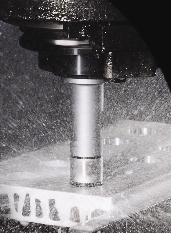
Boring a series of holes in an aluminum manifold at high rpm. Image courtesy Kennametal.

New boring technology also offers higher speeds. With the growth of high-speed spindles, boring heads are spinning faster. Yet the often nonsymmetrical construction of boring heads can make them wobble and vibrate when run beyond a few thousand rpm—especially single-edge finishing heads. Matt Tegelman, applications manager for BIG Kaiser Precision Tooling Inc., Hoffman Estates, Ill., explained that auto-balancing heads are a must-have for these situations. “They use a pinion gear to move a counterweight—as the cutting edge slides in one direction along with the cartridge (the insert holder), the weight moves opposite to it, keeping the head balanced for whatever diameter you 're boring.”

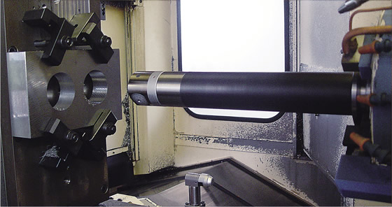
“For deep-hole finishing, we also recommend Smart Damper tools, which are used in conjunction with our auto-balance heads,” Tegelman said. The Smart Damper is BIG Kaiser’s solution for chatter, a common occurrence as boring depth increases. “Damping often becomes necessary at length-to-diameter ratios of 8:1 and higher,” he said. “Damping also allows for a heavier DOC and feed rate, sometimes two to three times that of an undamped boring head.”

The Smart Damper series covers hole diameters from 1.625 " to 4 ", and up to 16 " deep. For damping of bores smaller than that, Tegelman recommends a boring head together with a solid-carbide boring bar, preferably mounted in a hydraulic holder to utilize its superior damping characteristics.

“Boring heads typically use a locking mechanism to prevent movement during cutting,” Tegelman said. “As the insert wears and adjustment is needed, the operator must loosen the locking clamp, turn the dial plus or minus, and retighten the mechanism.”

Initial setup is often performed on a presetter, and in-process tweaks for tool wear are done at the machine. For tight-tolerance bores, the act of tightening the lock screw can affect the diameter. This is why Kaiser uses a special locking screw that doesn 't transmit the screw torque to the cartridge, thus minimizing the chance for clamping error, Tegelman said.

BIG_Daishowa_Smart_Damper_Action.tif

BIG Daishowa’s SmartDamper bored the hole on the left. The tool imparts a finer surface finish and offers longer tool life than boring tools without a damping system, such as the one that bored the substandard hole on the right, according to BIG Kaiser. BIG Kaiser Precision Tooling.

Kennametal Inc., Latrobe, Pa., addresses this potential problem differently. Marcus Paul, global product manager, hole finishing, said the company’s Romicron boring heads use an internal slide-gate mechanism to lock the head without a clamping screw. “With the Romicron, you just turn the adjusting ring until it clicks. There’s no risk of inadvertently changing hole diameter by over- or under-tightening a clamp. Each click correlates to 2µm of movement. If you need to adjust hole size by 10µm, it’s five clicks and you’re done.”

Kennametal also employs the technology on its Multicron boring system, which goes beyond conventional twin-bore roughing heads by holding multiple inserts.

“This system is a platform for special tooling,” Paul said. “Think of a cylinder liner, for example. You can have three to five inserts engaged at the same time, providing far more productivity. And since the Romicron mechanism moves all the inserts simultaneously, one click at a time, adjusting for wear is easy. " The heads also use a set of moveable balancing rings, which allow operation at spindle speeds up to 25,000 rpm, depending on the model.

Kennametal_Cylinder_Liner_1_Detail.tif

This Kennametal Multicron head uses five inserts to finish bore a cylinder liner in a single pass. Image courtesy Kennametal.

The “auto-lock” feature for Romicron and Multicron heads makes them suitable for closed-loop boring, which is often needed for unattended machining and to reduce machining interruptions. According to Paul, a fixture is mounted in the machine, one that engages the boring head’s adjustment ring. Feedback from in-process gaging is sent to software in the CNC, which tells the machine spindle how many degrees to rotate, thus adjusting the Romicron and Multicron heads the requisite number of clicks. This assumes the machining center has a spindle capable of programmable angular indexing, an option not available on all machines.

Without that capability, closed-loop operation is still a possibility. Tooling provider KOMET of America Inc., Schaumburg, Ill., blurs the line between a boring head and a profiling tool with its KomTronic U-axis system, which uses an internal stepper motor equipped with glass- scale feedback to adjust the boring head position during machining. Integration to the machine control is possible via a machine-mounted stator and a signal modulator, in essence turning the boring head into an additional machine axis.

“This system, in conjunction with inline gaging or probing, can be used for automated size adjustments,” said Michael Hunter, business development manager of drilling and boring tools for KOMET of America. “It goes beyond that, however. We have one customer machining three different bores in a transmission housing, all with the same head. It can also do contouring, reverse tapers or facing on the bottom of a bore. You could bore a Coke-bottle shape if you wanted to or even an asymmetrical shape. These would normally require a secondary operation on a CNC lathe.”

KOMET_Bluflex_group6.tif

KOMET’s MicroKom BluFlex has a digital display and uses a special key for adjustments. Image courtesy KOMET of America.

KOMET 's MikroKom BluFlex system offers another boring solution. Hunter said many traditional boring heads rely on a dial to indicate position, which is easy to misread when making adjustments. Instead, the BluFlex has a wireless digital display. This reads the actual position of the boring head and indicates whether the operator is turning the head in the wrong direction or over-adjusting it, virtually eliminating any chance of error. “The BluFlex displays big numbers,” Hunter said. “You insert the key, make the adjustment and see on the digital readout how much you’ve actually moved. Misreading the display is impossible, and it is also safer and more convenient for the operator than having to reach into the machine to read the display. A complete kit of boring bars and bridges is offered for the MicroKom BluFlex, allowing the machining of bores from 0.020 " to 8.465 ". Also, the same adjustment key and display can be used for several boring heads.”

Boring heads are among the most expensive tools in a shop. A single head may cost $1,000, while a kit with several cartridges and boring bars might set you back $4,000 or more. Automated, closed-loop systems cost much more. Boring heads are also limited, in that each one covers a specific range of hole sizes—a job shop might need several heads for each machine. Though nowhere near as accurate, this might be why many shops prefer to circular interpolate holes with an endmill and use boring as a last resort for deep or tight-tolerance holes. The investment in a good boring system, however, boosts productivity while improving holemaking accuracy. CTE


About the Author: Kip Hanson is a contributing editor to CTE. Contact him at (520) 548-7328 or by email: khanson@jwr.com.

Related Glossary Terms

  • boring

    boring

    Enlarging a hole that already has been drilled or cored. Generally, it is an operation of truing the previously drilled hole with a single-point, lathe-type tool. Boring is essentially internal turning, in that usually a single-point cutting tool forms the internal shape. Some tools are available with two cutting edges to balance cutting forces.

  • boring bar

    boring bar

    Essentially a cantilever beam that holds one or more cutting tools in position during a boring operation. Can be held stationary and moved axially while the workpiece revolves around it, or revolved and moved axially while the workpiece is held stationary, or a combination of these actions. Installed on milling, drilling and boring machines, as well as lathes and machining centers.

  • boring head

    boring head

    Single- or multiple-point precision tool used to bring an existing hole within dimensional tolerance. The head attaches to a standard toolholder and a mechanism permits fine adjustments to be made to the head within a diameter range.

  • chatter

    chatter

    Condition of vibration involving the machine, workpiece and cutting tool. Once this condition arises, it is often self-sustaining until the problem is corrected. Chatter can be identified when lines or grooves appear at regular intervals in the workpiece. These lines or grooves are caused by the teeth of the cutter as they vibrate in and out of the workpiece and their spacing depends on the frequency of vibration.

  • computer numerical control ( CNC)

    computer numerical control ( CNC)

    Microprocessor-based controller dedicated to a machine tool that permits the creation or modification of parts. Programmed numerical control activates the machine’s servos and spindle drives and controls the various machining operations. See DNC, direct numerical control; NC, numerical control.

  • coolant

    coolant

    Fluid that reduces temperature buildup at the tool/workpiece interface during machining. Normally takes the form of a liquid such as soluble or chemical mixtures (semisynthetic, synthetic) but can be pressurized air or other gas. Because of water’s ability to absorb great quantities of heat, it is widely used as a coolant and vehicle for various cutting compounds, with the water-to-compound ratio varying with the machining task. See cutting fluid; semisynthetic cutting fluid; soluble-oil cutting fluid; synthetic cutting fluid.

  • endmill

    endmill

    Milling cutter held by its shank that cuts on its periphery and, if so configured, on its free end. Takes a variety of shapes (single- and double-end, roughing, ballnose and cup-end) and sizes (stub, medium, long and extra-long). Also comes with differing numbers of flutes.

  • feed

    feed

    Rate of change of position of the tool as a whole, relative to the workpiece while cutting.

  • fixture

    fixture

    Device, often made in-house, that holds a specific workpiece. See jig; modular fixturing.

  • in-process gaging ( in-process inspection)

    in-process gaging ( in-process inspection)

    Quality-control approach that monitors work in progress, rather than inspecting parts after the run has been completed. May be done manually on a spot-check basis but often involves automatic sensors that provide 100 percent inspection.

  • lathe

    lathe

    Turning machine capable of sawing, milling, grinding, gear-cutting, drilling, reaming, boring, threading, facing, chamfering, grooving, knurling, spinning, parting, necking, taper-cutting, and cam- and eccentric-cutting, as well as step- and straight-turning. Comes in a variety of forms, ranging from manual to semiautomatic to fully automatic, with major types being engine lathes, turning and contouring lathes, turret lathes and numerical-control lathes. The engine lathe consists of a headstock and spindle, tailstock, bed, carriage (complete with apron) and cross slides. Features include gear- (speed) and feed-selector levers, toolpost, compound rest, lead screw and reversing lead screw, threading dial and rapid-traverse lever. Special lathe types include through-the-spindle, camshaft and crankshaft, brake drum and rotor, spinning and gun-barrel machines. Toolroom and bench lathes are used for precision work; the former for tool-and-die work and similar tasks, the latter for small workpieces (instruments, watches), normally without a power feed. Models are typically designated according to their “swing,” or the largest-diameter workpiece that can be rotated; bed length, or the distance between centers; and horsepower generated. See turning machine.

  • machining center

    machining center

    CNC machine tool capable of drilling, reaming, tapping, milling and boring. Normally comes with an automatic toolchanger. See automatic toolchanger.

  • profiling

    profiling

    Machining vertical edges of workpieces having irregular contours; normally performed with an endmill in a vertical spindle on a milling machine or with a profiler, following a pattern. See mill, milling machine.

  • turning

    turning

    Workpiece is held in a chuck, mounted on a face plate or secured between centers and rotated while a cutting tool, normally a single-point tool, is fed into it along its periphery or across its end or face. Takes the form of straight turning (cutting along the periphery of the workpiece); taper turning (creating a taper); step turning (turning different-size diameters on the same work); chamfering (beveling an edge or shoulder); facing (cutting on an end); turning threads (usually external but can be internal); roughing (high-volume metal removal); and finishing (final light cuts). Performed on lathes, turning centers, chucking machines, automatic screw machines and similar machines.

Author

Contributing Editor
520-548-7328

Kip Hanson is a contributing editor for Cutting Tool Engineering magazine. Contact him by phone at (520) 548-7328 or via e-mail at kip@kahmco.net.