Optimization software saves time
Optimization software saves time
Good optimization software must take into account all the known challenges to optimal machining, which include heat, vibration, deflection, chip buildup, material hardness and a machine tool's horsepower, torque, rigidity, spindle speed, maximum feed rate and accuracy. What's more, end users must also select the appropriate cutting tools and machining parameters.
Every CAM developer, machine tool builder and cutting tool manufacturer promotes the importance of cutting optimization. But what does "optimization" really mean? To stay competitive, manufacturing professionals must create NC programs that run as efficiently as possible and operate CNC machines to their full capabilities.
Achieving the shortest cutting time is related to feed rates, but that is only one of many factors. High-efficiency machining—cutting a part in the least amount of time—is the real goal. But as NC programmers and machinists know, there are many challenges to achieving optimal metal removal.
The known challenges to optimal machining include heat, vibration, deflection, chip buildup, material hardness and a machine tool's horsepower, torque, rigidity, spindle speed, maximum feed rate and accuracy. End users must also select the appropriate cutting tools and machining parameters. Good optimization software must take all these factors into account.
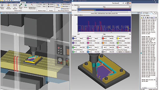
During optimization, the user can visually graph lots of information for analysis. In this example, the top of the graph shows the reduction in cutting time, per tool. In the lower "cutting conditions" area, the graph displays the volume-removal rate and chip thickness created with the original feeds and speeds. Image courtesy of CGTech.
Cutting at a greater depth often enhances efficiency, but the cutter may become overloaded and break or exceed the available horsepower on the machine. The most important parameter for achieving optimal machining is maximum chip thickness. Optimal cutting will only be achieved when the chip thickness is correctly controlled, based on the material's chip formation properties and the design of the applied cutter.
Thin chips are the most common cause of low productivity that results from poor tool performance. Thin chips can also cause premature tool wear due to friction and heat and breakdown of the cutting edge. On the other hand, chips that are too thick will overload the cutting edge, which can lead to breakage.
The key to achieving high-efficiency machining is to control chip thickness by varying the feed rate to achieve the desired result for each cutting condition. Effective optimization software knows the chip thickness throughout all cuts and takes advantage of thin-chip conditions by increasing the feed rate when it is beneficial to do so. Without rapid verification and optimization tools, this would be an overwhelming task—one that most CAM systems cannot perform.
Advanced CNC simulation software is a true knowledge-based system for high-performance machining. Through the simulation process, the software learns the exact depth, width and direction of each cut, and knows exactly how much material is removed by each cut segment. With this knowledge, motion is subdivided into smaller segments and optimal feed rates are assigned for each cutting condition. The software then outputs a new optimized toolpath, which has an identical motion path to the original but with an improved feed rate for the specific cutting condition.
Different feed-rate optimization strategies are appropriate for different materials and machining processes. Two variables to control when using software to optimize NC-program feed rates are volume of material and force on the cutter.
One way to almost instantly lower overall cutting time is to optimize the feed rate when the cutter is not engaging the workpiece. Many companies see a 15 percent reduction in machining time with this simple one-click step.
With a little more effort, the feed rate when the cutter engages the workpiece material can also be optimized. This method incorporates standard machining formulas, setting the feed rate based on the user's desired volume-removal rate, chip thickness and surface speed. These software settings can be automatically populated, for example, when cutting tool data is downloaded from MachiningCloud.
Alternatively, a setup wizard prompts a user simulating machining to input cutter settings. Essentially, intelligence is added to the cutter. All the settings for that cutter are stored in an optimization library. The settings are defined once, and, during each subsequent simulated machining operation with that cutter when it is applied with the same material and machine, the settings are instantly optimized.
There is also a learn-mode option for creating the optimization library with no setup required. For each cutter, the maximum volume-removal rate and chip thickness are identified and then used to determine a cutter's optimization settings.
An alternative technique uses material properties associated with the workpiece material and cutting tool substrate, plus cutting edge geometry and simulated cutter contact conditions, to predict cutting forces and chip load. Detailed charts can be viewed to determine problems that might arise for the specified chip load, force, spindle power and torque. The software then automatically adjusts the feed rates to stay within the desired cutting force, chip load and power limits.
The program interpolates cutting conditions using a proprietary set of materials coefficients to account for the strength of materials, as well as the physics of chip formation and the effects of friction and temperature. The materials coefficients are derived from physical machining characterization tests and do not rely on extrapolating from theoretical results.
The methods mentioned produce optimized feed rates that offer similar benefits: finer surface finishes and reduced cycle times, tool wear and tool breakage. Once a cutter and workpiece material are characterized, the characterization is suitable for a broad range of cutters and machines applied in future machining operations.
Optimizing by volume of material does not require materials to be characterized. Instead, optimization relies on the user's machining knowledge to set his desired machining conditions, or else it is "learned" from the NC program. It is most effective when ideal cutting conditions are known for each cutting tool, material and machine.