Machine Technology: Manually measuring 5-axis centerlines

Author Michael Cope
Published
October 09, 2017 - 02:15pm

In 5-axis machining, accurate rotary axis centerlines are critical, so regularly measuring and verifying these values is also critical. While the best course of action is to measure the machine using a high-tech system intended for this purpose, in a pinch you can use a manual process.

Common shop tools, such as test indicators, 1-2-3 blocks and edge finders, give close-enough-for-now verification of centerline measurements on trunnion-style and add-on 5-axis machine configurations.


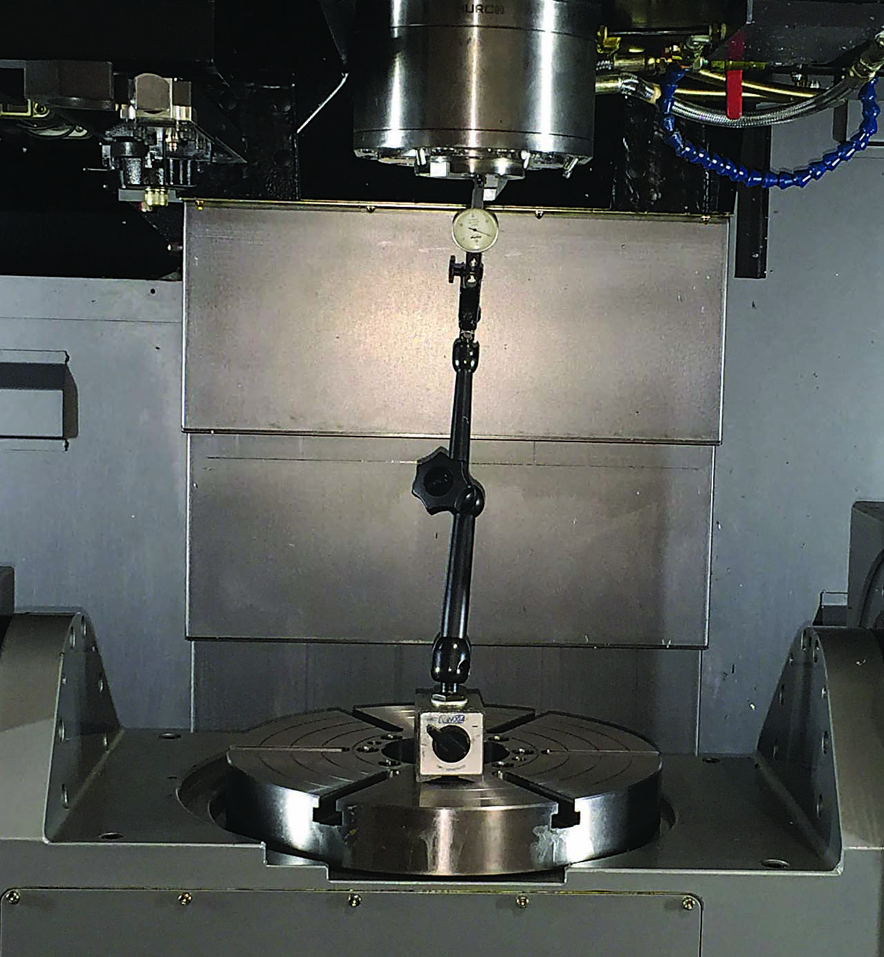
Figure 1. To find the true X and Y centerlines of rotation for the C-axis table, place the indicator and magnetic base on the table and indicate the inside of the spindle nose by rotating the C-axis table. Images courtesy of Hurco.


In all 5-axis centerline measurement procedures, the goal is to identify the location of an X-, Y- or Z-axis machine position for both the rotary and tilting axes. For example, on an A-axis trunnion machine, you need to locate the X-Y centerline location for the C-axis (the point in space that the axis rotates around) and the Y-Z centerline location for the A-axis. Although each machine tool builder might have a different set of rules for how these positions are used and the point from where they are measured, the basic idea of how to find these values is the same.

Before you follow the procedures outlined here, it is important to understand the origin point that you need to use when measuring these distances. Although the X- and Y-axis measurements are almost always measured from the machine’s home position, the Z-axis values could be different. For example, some builders refer to the spindle gage line, but others might use the face of the spindle nose itself. Regardless of the builder, knowing this information is critical, and it can be obtained easily by calling your local machine service provider.

A-axis trunnion machines are the most popular configuration, so, because of space limitations, I will limit my discussion to them. 

You will need a test indicator, an edge finder and a couple of 1-2-3 blocks or a dial height gage for setting tools. Finding the X-Y centerline will be fairly straightforward and probably be the same for machines from all builders. Although the Z-axis results may vary, the following procedure will help you find the
C-axis X-Y centerline for your machine:

  1. Run an indicator across the surface of the C-axis table to ensure that the A-axis is flat.
  2. To find the true X and Y centerlines of rotation for the C-axis table, place the indicator and magnetic base on the table and indicate the inside of the spindle nose by rotating the C-axis table (Figure 1).
  3. Note the current X-Y machine position. This location is the X-Y centerline for the C-axis.

The following steps are for finding the Y-axis offset distance:

  1. Set a part setup zero point at the X-Y location found in the C-axis centerline (step three in the previous procedure). You will use this new X0.000" Y0.000" part zero reference location in the following steps.
  2. Position the X and Y axes at the new part zero location (X0.000" Y0.000") indicated in step one.
  3. Swing the A-axis to -90°.
  4. Use an edge finder to locate the face of the table. Don’t forget to adjust for the diameter of the edge finder. The center of the spindle must be located directly over the edge of the table.
  5. Jot down the Y-axis value shown on the part display on the digital readout. You will use this value later to calculate the A-axis centerline value. For example: -0.004" (-0.102mm).

Here is a tip: If the Y-axis had to be jogged negatively (toward the operator) to contact the table surface, then the centerline of the A-axis is below the table surface when the A-axis is positioned at 0°. However, if the Y-axis had to be jogged in the positive direction (away from the operator), then the centerline is above the table surface when the A-axis is positioned at 0°.


Figure 2. In this machine, the A-axis can tilt 110° forward but only 30° in the opposite direction.


The Y-axis centerline for the trunnion A-axis should be the same value found in the C-axis procedure. Even though it’s possible that the actual position is slightly different, you cannot verify the precise position because of the tilting limitations (in one direction) on most AC-style trunnion machines. For example, Figure 2 shows that the A-axis can tilt 110° forward but only 30° in the opposite direction. Because of this limitation, you can’t locate the true Y-axis centerline. 

However, this procedure is intended to provide the needed information in a pinch. When finding the A-axis Z centerline, you must locate the surface of the C-axis table to determine the Z-axis centerline. Yet the actual procedure for finding the Z-axis centerline will vary depending on the location from where the centerline is measured, which might differ depending on the particular machine builder. 

For example, Hurco refers to the gage line of the spindle, which is a specific location on the spindle taper. Other machine builders refer to the face of the spindle nose. This is why a complete understanding of a particular machine is critical. Therefore, step three is intentionally vague because I don’t know exactly what will make contact with the 1-2-3 blocks or height gage used. (It could be the face of the spindle or the tip of a master length-reference tool.)

  1. Return the A-axis to 0°.
  2. Place 1-2-3 blocks or a dial height gage on the table surface so the blocks or gage can be reached when the Z-axis is jogged all the way negative, which may require stacking the blocks, depending on the machine travels.
  3. Jog the Z-axis down until contact is made with the top of the 1-2-3 blocks or the height gage.
  4. Note the current Z-axis machine position.
  5. Using the position from step four, account for all necessary items involved to determine the exact location of the table surface. (Account for the length of the master length reference tool if used, the 1-2-3 blocks or dial height gage, and any gage blocks.) The resulting value will be the distance to the surface of the C-axis table.
  6. Use the value found in the Y-axis offset distance procedure (where you used the edge finder to locate the surface of the table), and add or subtract the value, as needed, to determine the location of the Z-axis centerline.

Related Glossary Terms

  • edge finder

    edge finder

    Gage mounted in the spindle of a vertical mill and used, while rotating, to find the center of a part relative to the toolholder.

  • flat ( screw flat)

    flat ( screw flat)

    Flat surface machined into the shank of a cutting tool for enhanced holding of the tool.

Author

Hurco Cos. Inc.
317-298-2613

Michael Cope is product technical specialist at Hurco Cos. Inc., Indianapolis. Contact him at (317) 298-2613 or copem@hurco.com. This column was adapted from the upcoming second edition of his book The Power of Five: The Definitive Guide to 5-Axis Machining.