Effectively Reaming Nickel-Base Alloys
Nickel-base alloys reward a slow, stable reaming process with close control of stock allowance, speed, feed, and coolant. This guide covers the main setup priorities.
Quick take: Nickel-base alloys punish aggressive reaming with heat, deflection, and poor hole quality. This guide works best when it is used with feeds-and-speeds math and material-behavior references rather than as a stand-alone rule sheet.
Related references: Cutting Speed and Feed Rate Guide, Understanding Hardness in Metalworking, and Coefficient of Linear Thermal Expansion: Machining Guide.
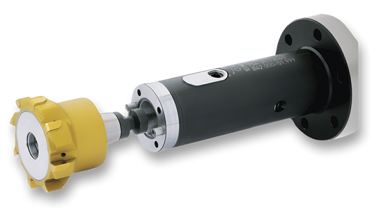
Courtesy of KOMET of America
The Dihart Reamax TS carbide-tipped reamer is available from KOMET of America.
Effectively reaming nickel-base alloys requires a slow and steady approach.
When a metal part must offer low weight, corrosion and oxidation resistance and high strength at high temperatures, part designers often turn to nickel-base alloys. These materials, along with iron- and cobalt-based materials, are considered heat-resistant superalloys.
However, the properties that make nickel alloys desirable for extreme environments, such as those found in pressurized-water reactors at nuclear power plants and in aerospace turbocharger rotors, make the metals a challenge to machine. That’s because the high pressure the cutting tool exerts on the workpiece during machining produces a stressed and deformed surface layer, explained Adrian von Rohr, Dihart product manager for KOMET of America Inc., Schaumburg, Ill. This deformation causes the workpiece surface to harden, slowing the machining process.
“Even under the best conditions, stresses may be produced that distort the work,” von Rohr said. “For maximum dimensional stability, it is best to rough the part almost to size, stress-relieve it and then finish it to size.”
Particularly difficult-to-machine nickel alloys include Incoloy 901, Nimonic 80 and 105, and Inconel 625 and 718. The latter is a precipitation-hardenable nickel-chromium alloy with excellent creep-rupture strength at temperatures up to 1,300° F. It is used in gas turbines, pumps and rocket motors, according to ESPI Metals, Ashland, Ore., a supplier of high-purity metals and metal compounds for research purposes. The nominal composition of Inconel 718 includes, among other elements, 52.50 percent nickel, 19.00 percent chromium, 17.00 percent iron, 3.05 percent molybdenum and even a bit of titanium, at 0.90 percent.
Because these extreme-environment parts often require high-quality holes—with an H7 international size tolerance grade or better—part manufacturers commonly employ reaming to meet surface finish, size and concentricity requirements. For example, an H7 tolerance for an 18mm-dia. hole is 0 “/+0.0007 “.
“As the hole gets bigger, the tolerance range gets larger,” said Jacob Miller, product manager for Allied Machine & Engineering Corp., Dover, Ohio. The cutting tool manufacturer recently added replaceable-head reamers from S.C.A.M.I. to complement Allied’s monoblock and ring-style reamer offerings from the same Italian manufacturer.
Although high-performance drills can produce high-quality holes, reaming is required for a tighter diameter tolerance. Indexable-insert drills typically achieve a tolerance as tight as 0.008 ” and solid-carbide drills achieve a 0.002 ” tolerance, von Rohr noted, but solid-carbide, carbide-tipped and indexable-inserts reamers attain a tolerance of 0.0004 “. KOMET makes solid-carbide, carbide-tipped and indexable-insert reamers.
Take it Slow
Similar to other machining processes, reaming nickel alloys requires a significantly slower cutting speed compared to most other materials, Miller noted. “Usually it’s between 60 and 80 sfm for coated carbide,” he said.
Because nickel alloys tend to workharden, a slower speed reduces friction and heat generation, von Rohr added. Just as a drilled hole guides a reamer, drilling speed can direct reaming speed. A rule of thumb is to ream at about two thirds the drilling speed, he noted.
Others interviewed concurred that reaming nickel alloys is a slow process but some offered slightly different recommendations. Tom Edler recommends reaming Inconel at 80 to 100 sfm. He’s the national deep-hole drilling, reaming, thread milling, ITS bore and oil field thread chasers products manager for Iscar Metals Inc., Arlington, Texas. Iscar’s BAYO T reaming system is suitable for nickel-alloy applications. While the speed is slow, the feed can be a different matter. “The design of the tool allows for aggressive feed rates, typically 20 to 30 times faster than conventional reamers,” Edler said.
Compared to reaming steel at a cutting speed of about 650 sfm, 200 sfm is appropriate for Inconel 718 when applying BTA Heller Inc.’s float reaming, or skive, tool, noted Mark Sollich, president and CEO of the Troy, Mich., company. BTA Heller states that the tool body holds a floating cutter magazine with two cartridges and two indexable inserts that oppose one another and have diametrical adjustment of 0.080 ” to 0.118 “, depending on the tool diameter. Each insert has four cutting edges.
“A float reaming tool is designed to follow the existing hole and give uniform size, finish and wall thickness from start to finish, producing a true round bore,” Sollich explained. “When you start into the bore, you introduce hydraulics to the tool, expanding the floating magazine, or cutters, to whatever size you require and skiving through the part with high-volume coolant running on the tool OD, which flushes chips away from the cutting edges. When you get to the end of the bore, you turn off the hydraulics, collapsing the cutters, and pull the tool back without leaving any scratches or marks inside the bore.”
Courtesy of Allied Machine & Engineering
The new S.C.A.M.I. replaceable-head reamers complement Allied’s monoblock and ring-style reamer offerings.
The float reaming tools, which can open existing bores up to 1⁄8 ” on diameter, are applied only in a deep-hole drilling machine and can ream holes 100 diameters deep or more, according to the company.
Sollich added that the tool’s double-effective cutting configuration allows users to substantially increase the feed rate versus a single-cutter reamer. For Inconel 718, he recommends a feed of 0.040 to 0.060 ipr.
According to von Rohr, too low a feed rate results in glazing, or workhardening, of the workpiece and excessive tool wear, while an excessive feed reduces the accuracy of hole dimensions and surface finish quality. He recommends a feed from 0.0015 ” to 0.004 ” per flute per revolution when reaming nickel alloys.
Gary Schmidt, applications engineering for M.A. Ford Manufacturing Co. Inc., Davenport, Iowa, recommends basing reaming parameters on those for holemaking with carbide drills, cutting the reaming speed in half and doubling the feed. The increased feed will load the reamer and prevent it from rubbing and wearing prematurely, he noted. M.A. Ford produces standard solid-carbide reamers from 0.013 ” to 5⁄8 ” and specials up to 1¼ “.
Geometries at Work
In addition to running at the correct feed, applying reamers—which cut only on the bevel and taper leads and not on the lands—with up-sharp cutting edges and positive rake angles will shear nickel alloys rather than push the material. “The biggest concern is making sure you have a sharp tool geometry to minimize the amount of heat you produce,” said Allied’s Miller.
To support those sharp edges, the relief angles must be slightly less steep than on reamers for less demanding materials, according to M.A. Ford’s Schmidt. Reamers typically have 3° to 5° relief angles, whereas 1° to 3° is more appropriate on tools for nickel alloys.
“What we’re seeing on some of the newer reamers is just a bit of a cylindrical margin, so, if you have chipping, the cutting edges are backed up,” Schmidt added. With that design on a reamer with a smaller relief angle, toolmakers place more support on the back of the cutting edge, making the edge stronger.
The BAYO T reaming system from Iscar Metals is suitable for nickel-alloy applications.
Because chip control can be problematic when reaming nickel alloys, chipbreaker geometry is beneficial, according to Sollich. He noted BTA Heller’s float reamers have a manual chipbreaker held with an insert clamp. “The chipbreaker width can be adjusted based on the workpiece material,” he said. “If you’re reaming a material that tends to be tough as far as chip control, you tighten the chipbreaker to a smaller width, maybe 0.040 “.”
On conventional reamers, a chipbreaker is effective for controlling chips but it reduces tool life compared to a reamer without one, according to KOMET’s von Rohr. A chipbreaker may not even be required to control nickel alloy chips. That’s because, as the material workhardens, it becomes more brittle and tends to break from the parent material before becoming long and stringy, he added. “The nickel itself almost acts like a chipbreaker.”
A reamer’s geometric configuration also helps minimize chatter—especially unwanted in a finishing operation. Reamers frequently have asymmetrical flute spacing to disrupt the natural-harmonic-frequency generation that causes chatter during machining, von Rohr noted. He added that the flute design can aid machinability when interrupted cutting, such as when reaming cross-holes. “Dihart always uses asymmetrical-flute spacing for our high-performance reamers,” he said.
Iscar’s Edler indicated that BAYO T reamers have uneven flute spacing, with two flutes directly across from each other and the remaining ones varied. “It’s definitely to avoid harmonics,” he said.
When controlling chips, a reamer’s lead angle also plays a critical role. In addition to possibly a 45° lead angle, a reamer might have a double, or compound, angle, with a 20° lead as well, to reduce the cutting force and enhance chip control by generating smaller chips, Edler explained. “The compound angle can be anything we need it to be to solve the chip control issue.”
He added that the lead angle varies, depending on whether the hole being reamed is a through- or blind-hole. When reaming a through-hole, a 45° lead angle rolls the chips forward—ahead of the tool and out the hole. In a blind-hole, a 20° lead directs the chips back up the flutes and out the hole.
Not all influential reamer geometries can be readily seen. Coolant channels facilitate metalworking fluid flow to effectively evacuate chips and can also vary in design depending on what type of hole is being reamed. When it’s a blind-hole, Schmidt pointed out that M.A. Ford engineers the though-coolant design so it directs the flow backward, whether through one central channel or two holes, and helps bring chips out the top of the hole instead of sending them to the bottom.
Cool Cutting
Because nickel-base alloys withstand high temperatures, not much heat enters the material and the heat that does enter is carried away when chips are made. Therefore, coolant is needed to keep cutting edges from overheating and causing premature tool failure while helping to clear chips.
Review the print ads from this magazine to continue
This quick advertiser review unlocks the rest of the article and keeps the full-screen reader focused on the ads instead of the page chrome.

