Cutting back spotfacing cycle time
Cutting back spotfacing cycle time
END USER: Fulflo Specialties Inc., (937) 783-2411, www.fulflo.com. CHALLENGE: Increase tool life in back spotfacing of stainless steel hydraulic relief valve bodies. SOLUTION: Custom tool for difficult-to-machine workpiece materials. SOLUTION PROVIDER: Heule Tool Corp., (513) 860-9900, www.heuletool.com
--------------
END USER: Fulflo Specialties Inc., (937) 783-2411, www.fulflo.com. CHALLENGE: Increase tool life in back spotfacing of stainless steel hydraulic relief valve bodies. SOLUTION: Custom tool for difficult-to-machine workpiece materials. SOLUTION PROVIDER: Heule Tool Corp., (513) 860-9900, www.heuletool.com
---------------
Established in 1912, Fulflo Specialties Inc., Blanchester, Ohio, is one of a handful of companies that helped pioneer modern fluid power technology. The company patented its guided-piston, direct-acting hydraulic relief valve in 1935 and pilot valve-controlled relief valve in 1943.
Fluid power relief valves remain the sole products made in Fulflo's 42,000-sq.-ft. shop. The company's products are used in hydraulic systems for oil and gas, wind energy, aerospace, marine and off-road equipment applications, among others. The valves ensure safe fluid system operation by opening in proportion to potentially dangerous pressure increases upstream and are manufactured according to ASME standards for hydraulic components.


Courtesy of Heule Tool
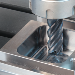
A stronger tool with an improved design significantly reduced cycle times and extended tool life when back spotfacing stainless steel hydraulic relief valves at FulFlo Specialties.
Fulflo produces valves with bores from 1" to 4" in diameter in steel, cast iron and 316 stainless steel. It manufactures valve springs and other internal components and buys valve body castings, which require machining of multiple features. Performed on Mazak Ultra 650 horizontal machining centers, valve body machining includes milling, drilling, boring, ring grooving and threading, noted Rick Collett, plant manager.
One operation that was proving difficult was back spotfacing of bolt holes on the flanges of 316 stainless valves, according to Collett. "Hole diameters on stainless valves range from 5⁄8" to 1"," he said. "The holes require back spotfacing to allow use of washers or other fastener components, and each valve body requires four or eight holes with back spotface diameters of 1.37" to 1.78" and depths up to ¼"."
Collett added that cycle times for completing stainless valve bodies were as long as 69 minutes, and back spotfacing consumed a big chunk of that. "We were using hinge-type tools for back spotfacing, and you had to run them through the hole and then reverse the spindle to get them to open," he explained. "On stainless valves, tool life was maybe two pieces—if we were lucky."
That was assuming the tool didn't fail catastrophically. "With the hinge-type tool, any small imperfection in the tool would cause it to break," Collett said. "Also, sometimes the tool would be open just enough to break when we tried to put it through the hole, so we wound up with a broken tool and a damaged part."
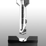
Looking to improve the operation for stainless valve bodies, Fulflo hit on SOLO back counterboring tools from Heule Tool Corp., Cincinnati. Used primarily in aerospace turbine applications and for machining flanges and valves, the custom tools can produce forward and back spotfaces and counterbores, as well as special form countersinks and other contour forms. Using internal weights enclosed in a sealed tool head and a radial pin drive system that activates and locks the blade into the cutting position, the tools open when spindle speed is reduced and close when it is sped back up. The blade slides in and out of the housing window along the Y-axis, and coolant through the tool comes out the blade window to flush chips and debris away from the blade activation point. Cutting forces are distributed along the entire blade window.
The tool previously in operation used a hinge system to open and close its cutting mechanism. Cutting forces were centered on the hinge, resulting in a weaker tool and, too often, premature failure.
The tooling switch significantly reduced cycle time. "Machining time on the valve bottoms, which includes boring the hole to size, drilling and back spotfacing, dropped from 39 minutes to 15," Collett said. "And that's running at the low end of the recommended speed and feed range for the back spotfacing tools."
Tool life increase was equally impressive. "So far we've run 420 stainless valves, up from 2 on the old tool and we've only indexed the two-sided inserts once," Collett reported.


