
In This Magazine

History of Hertz, Newton and Pascal
In the fourth installment of Metric Matters, Dr.
Perks of fiber lasers
Pulsed fiber lasers offer numerous advantages compared with traditional fabrication methods.
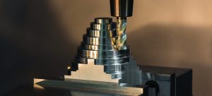
The allure of aluminum
Effectively milling aluminum requires balancing all elements of a cutting tool.

Tool coatings covered
Many toolmakers have reasons to bring coating capabilities in-house.

CTE subscribers still at work
More than 97% of companies surveyed among Cutting Tool Engineering's subscribers reported that they remain open for business.
Buying an established shop: People & Companies
The machines might be dated, but existing customers and experienced employees beat starting from scratch.
Ballscrew breakthrough
With technology under development at Karlsruhe Institute of Technology in Germany, machining firms soon may be able to improve the process of spotting…
Finding the source of chatter
The Grinding Doc offers a simple test to determine the cause of chatter.
Learn the ins and outs of centerless grinding
Any machinist probably has heard of centerless grinding, but it is an obscure process often only familiar in name.
Moving machines via hovercraft
AeroGo Inc.'s air caster system keeps expensive epoxy-coated floors looking good.
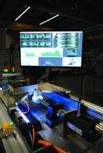
Detect spindle anomalies: Digitalization & Industry 4.0
The Artis GEMDS system helps shops reduce scrap and improve productivity.
Magazine chronology
Browse issues
PREVIOUS ISSUE
June 2020
June 15, 2020
CURRENT ISSUE
July 2020
July 15, 2020
NEXT ISSUE
August 2020
August 15, 2020
July 2020
