Broaching a blind keyway with an inserted tool
Being able to broach a blind keyway while keeping the part on the same CNC machine tool used to perform the other machining operations provides a significant improvement in setup, reliability and accuracy, compared to moving the part to a dedicated broaching machine.
Being able to broach a blind keyway while keeping the part on the same CNC machine tool used to perform the other machining operations provides a significant improvement in setup, reliability and accuracy, compared to moving the part to a dedicated broaching machine.
That’s according to Kevin Sanieski, CNC tooling system lead for The duMONT Co. LLC, Greenfield, Mass. One effective method is to use broaches that accept inserts, and the toolmaker offers those in its Minute Man line for application on CNC lathes and machining centers.
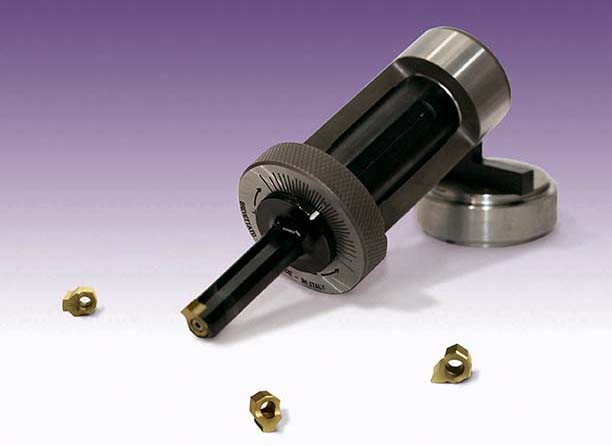
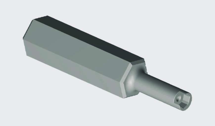
Minute Man broaches from duMONT accept keyway inserts, as well as slotting and special inserts,
for application on CNC lathes and machining centers. Image courtesy of duMONT.
“You can basically run them in any lathe or milling machine,” Sanieski said. “Obviously, the bigger and more rigid the machine, the better the tools will operate.”
Inserts are available to produce blind-keyway widths from 3/32″ to ¾” and from 2mm to 25mm.
The challenge when applying this type of tool is that if a user cuts a blind keyway, simply retracts the tool from the cut and then continues to broach, the chips continue to build up at the bottom of the keyway and the insert inevitably becomes damaged, Sanieski explained. Therefore, the company provides a CNC program with its keyway broaching system that promotes continuous tool movement and cutting while eliminating the need to manually clear chips.
“Specifically, in the blind-keyway situation, you didn’t really have an option before CNC systems came along,” he said. “We have found that ramping that tool out at a 45° angle, or thereabouts, helps keep that insert intact and clears the chip out of the way.”
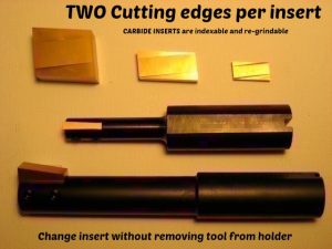
CNC Broach Tool offers indexable-insert tools for broaching blind keyways. The tools have setscrews
on the side, but the inserts are open face. Image courtesy of CNC Broach Tool.
Sanieski added that the broaching system is not only suitable for generating keyways but also splines, squares, hexes and other internal and external features. “Anything you can think of, we can match a profile.”
A Different Approach
John Gardner, owner of CNC Broach Tool LLC, Marina Del Rey, Calif., agreed that users can ramp, or taper, an indexable-insert broach out of a blind keyway when broaching it, but maintains that the programming required to do so is difficult to perform. In addition, the design of the broaching tool CNC Broach Tool offers isn’t well-suited for ramping out of the cut.
When broaching on a lathe, the workpiece is positioned horizontally and gravity causes chips to fall down and away. Not so when broaching on a mill. With a mill, Gardner recommends creating a cross-hole, groove or notch relief in the part—an open area to push the chips into. The relief area needs to be large enough that coolant doesn’t simply flush and pack the chips into it, however. If the relief area is not large enough, the tool will pound into those packaged chips and potentially cause a crash, he said, adding that coolant flushes the chips right through a cross-hole and avoids that.
“We want to have enough relief space so you’re not pounding chips in there,” Gardner said. “That’s the ultimate goal for blind-keyway broaching.”
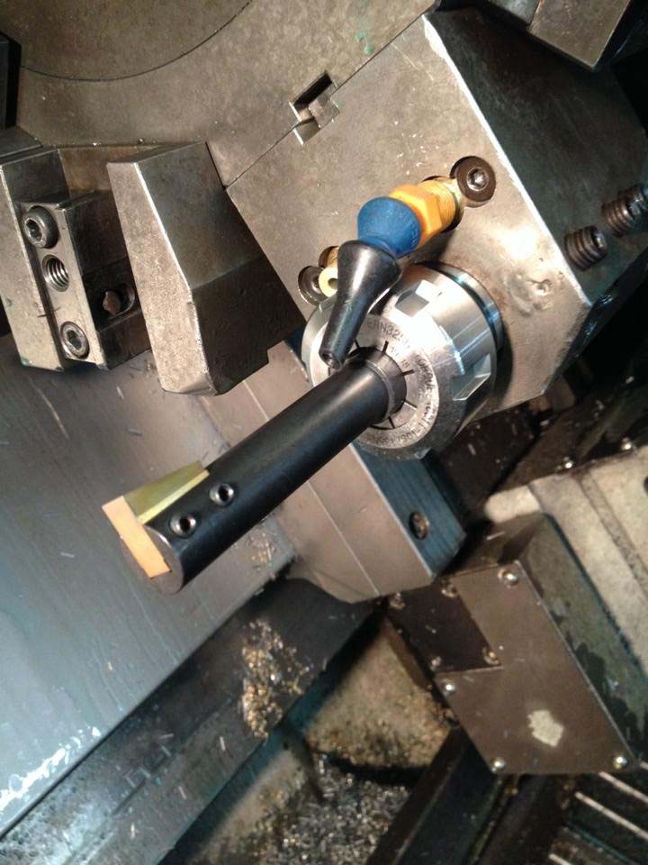
The duMONT Minute Man tooling system allows users to broach through and blind keyways,
keyways in a tapered bore and shaped or splined holes. Image courtesy of duMONT.
CNC Broach’s tools have setscrews on the side, but the carbide inserts are open face, Gardner explained, and the design of the insert directs the cutting force down into the tool centerline and seats the insert down and back in the tool body’s pocket. This design protects the machine if the insert, which has two cutting edges, experiences a lot of pushback or chips buildup in the relief area, he said.
The company states that it designed the insert to pop out of the tool pocket to protect the machine spindle if there is not enough relief space. “Don’t get mad and blame the tool,” Gardner stated. “This is a clue that you do not have enough relief space or the chips are not evacuating the relief space and you are pounding into them.”
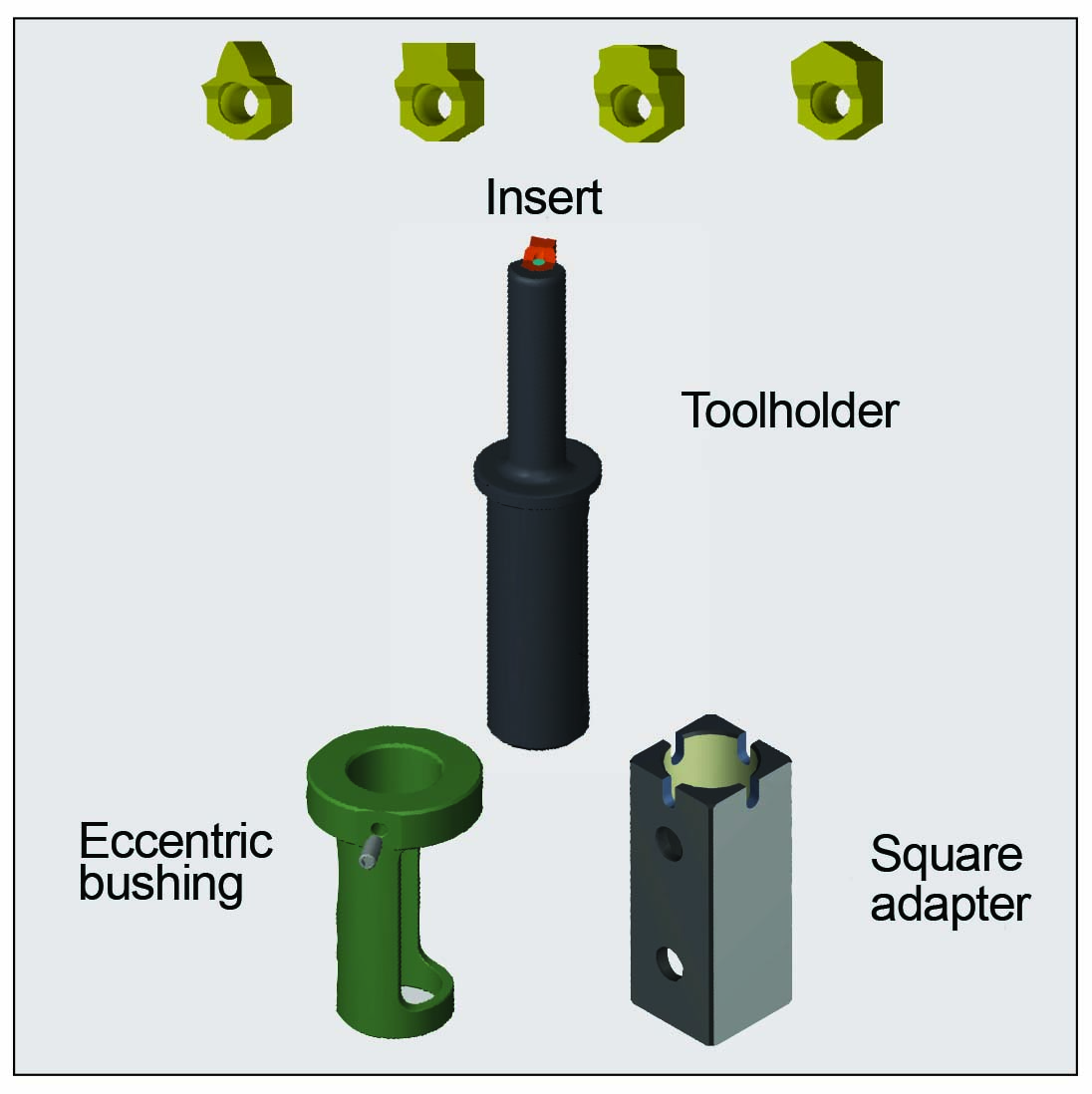
The duMONT sharpening stem holds an insert securely in place as the cutting edge
of the insert is resharpened at its original angle. Image courtesy of duMONT.
Ron Odekirk, production manager for Muthig Industries Inc., Fond du Lac, Wis., a parts manufacturer that applies tools from CNC Broach to broach blind keyways, described the toolpath as rectangular, and said the tool is fully withdrawn from the workpiece when it retracts from the hole after each cut.
When the tool comes out of the hole, the insert shouldn’t touch any metal, Odekirk said, noting the rectangular toolpaths get wider and wider as the broach progresses and makes the keyway deeper and deeper.
Need for Speed
Gardner compares blind-keyway broaching with an indexable-insert tool on a CNC machine to chopping down a tree with an ax. “If you swing the ax really slowly, the ax bounces off of the tree, but if you swing it fast, the ax bites and cuts,” he said.
“Speed is your friend” when broaching, Gardner added, but many users are afraid of hurting their CNC machines when applying the tools. Depending on the workpiece material, “I have to constantly remind them that they’re only taking a 0.001″ depth of cut,” he said. “It’s just a very light shave. There is virtually no force involved. You could push that through with your hand.”
Nonetheless, Gardner pointed out that even though the operation involves taking a light DOC, it’s essentially a “controlled crash. You’re blasting the tool in there. Broaching is a very shocking operation.”
For example, Muthig Industries applies broaches from CNC Broach at 550 ipm (13.97 m/min.) when producing blind keyways in parts made of relatively soft cold-rolled steel. (See sidebar below).
To achieve the most-effective cutting speed, Gardner suggests holding the broach body in an ER collet with the backstop held directly in a CAT 40 or 50 spindle. He recommends to never hold the shank of the ER collet in a VDI boring bar sleeve to avoid generating taper in the ceiling of the keyway.
Review the print ads from this magazine to continue
This quick advertiser review unlocks the rest of the article and keeps the full-screen reader focused on the ads instead of the page chrome.