Using stability lobe diagrams

Author Dr. Scott Smith
Published
May 01, 2009 - 12:00pm

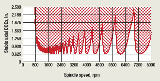
Do you recognize the diagram below? You should, because it represents the productivity of your machine tools. It’s a stability lobe diagram and it summarizes cutting performance in metal-removal operations. This specific diagram was made for milling with a 2-flute carbide endmill in a 40-taper shrink-fit holder in a 7,200-rpm machining center. It was made for a particular radial DOC (in this case slotting) in 7050 T-7451 aluminum.

Courtesy of Manufacturing Laboratories

A typical stability lobe diagram.

The cutting conditions in red-shaded areas will cause chatter, characterized by heavy vibration, tool damage, poor surface quality and scrapped workpieces. The conditions in the white areas will be stable, producing no chatter.

When spindle speed is low enough, less than about 800 rpm in this case, it is possible to take large axial DOCs without causing chatter. As spindle speed increases, the chatter-free axial DOC decreases, in this case to about 0.3 " in the 1,600-rpm range. Any slots deeper than this will cause chatter. As the spindle speed increases further, the permissible axial DOC increases again, but only in specific spindle speed ranges. For example, there are large, stable pockets around 4,800 to 4,900 rpm, around 5,600 to 5,700 rpm and around 6,700 to 6,800 rpm. There will be another pocket near 8,400 rpm as well, but that is higher than the top speed of this spindle.

At the best of these speeds, the axial DOC can be more than four times higher than at the worst speeds. The metal-removal rate and the machine productivity can be greatly increased by using the right spindle speed. The stable pockets get taller and wider as the spindle speed increases, which is one of the major factors driving machine tool builders and users toward high-speed machining.

A stability lobe diagram like this one can be created for every tool in every toolholder in every machine. I say “like this one” because although all stability lobe diagrams have similar characteristics, details differ for each application because assembled structures differ.

Chatter arises from a dynamic interaction between the cutting process and the machine structure. The machine structure is stiff, but not infinitely so. As the cutting tool’s teeth pass the workpiece, deflections between the tool and workpiece leave an imprint, or waviness, on the surface. The following teeth encounter the waviness and experience a variable cutting force, which causes vibration and leaves another wavy surface. Depending on the characteristics of the assembled structure and on the cutting conditions, the waviness can get worse, producing chatter, or it can improve, becoming more stable.

Knowing where the “good” speeds are and knowing the permissible DOCs can allow operators to double or triple mrr without any modification of the existing tools, toolholders or the machine. However, nearly every part of the machine structure plays a role in the specific appearance of the stability lobe diagram, including the:

 length and diameter of the tool,

 number of cutting edges,

 tool/toolholder interface,

 toolholder style,

 toolholder/spindle interface,

 drawbar force,

 size, material and arrangement of the spindle bearings,

 maximum spindle speed, and

 torque and power curves.

It is the performance of the assembled machining system that counts, not any one piece. There is no general chatter-free tool, no best number of teeth and no best kind of toolholder.

There is also no general best machine, spindle interface or spindle speed. Rather, all of the machining system’s elements contribute to the stability lobe diagram. While suppliers of machines, tools and toolholders try to optimize their specific products, it is not until the pieces come together at the process that the performance is determined. Some tools and holders match one machine or process better than another. Sometimes, large stable zones correspond to the programmed spindle speeds, but far more often this is not the case.

The stability lobe diagram controls the performance of milling and many other metal-removal operations. Without the stability lobe diagram, machine tool users are guessing, and guessing represents a huge productivity loss. Trial-and-error programming, selection of unproductive cuts, scrap and damage to the machine are the hidden costs of insufficient information. Competitive shops need stability data for all their tools in all their machines. Stability lobe diagrams are a powerful key to unlocking the full potential of machine tools. (Note: Future columns will examine the information needed to create stability lobe diagrams and how shops can develop them or have them developed.) CTE

About the Author: Dr. Scott Smith is a professor at the William States Lee College of Engineering, University of North Carolina at Charlotte, specializing in machine tool structural dynamics. Contact him via e-mail at kssmith@uncc.edu. 

Related Glossary Terms

  • chatter

    chatter

    Condition of vibration involving the machine, workpiece and cutting tool. Once this condition arises, it is often self-sustaining until the problem is corrected. Chatter can be identified when lines or grooves appear at regular intervals in the workpiece. These lines or grooves are caused by the teeth of the cutter as they vibrate in and out of the workpiece and their spacing depends on the frequency of vibration.

  • cutting force

    cutting force

    Engagement of a tool’s cutting edge with a workpiece generates a cutting force. Such a cutting force combines tangential, feed and radial forces, which can be measured by a dynamometer. Of the three cutting force components, tangential force is the greatest. Tangential force generates torque and accounts for more than 95 percent of the machining power. See dynamometer.

  • endmill

    endmill

    Milling cutter held by its shank that cuts on its periphery and, if so configured, on its free end. Takes a variety of shapes (single- and double-end, roughing, ballnose and cup-end) and sizes (stub, medium, long and extra-long). Also comes with differing numbers of flutes.

  • gang cutting ( milling)

    gang cutting ( milling)

    Machining with several cutters mounted on a single arbor, generally for simultaneous cutting.

  • machining center

    machining center

    CNC machine tool capable of drilling, reaming, tapping, milling and boring. Normally comes with an automatic toolchanger. See automatic toolchanger.

  • metal-removal rate

    metal-removal rate

    Rate at which metal is removed from an unfinished part, measured in cubic inches or cubic centimeters per minute.

  • milling

    milling

    Machining operation in which metal or other material is removed by applying power to a rotating cutter. In vertical milling, the cutting tool is mounted vertically on the spindle. In horizontal milling, the cutting tool is mounted horizontally, either directly on the spindle or on an arbor. Horizontal milling is further broken down into conventional milling, where the cutter rotates opposite the direction of feed, or “up” into the workpiece; and climb milling, where the cutter rotates in the direction of feed, or “down” into the workpiece. Milling operations include plane or surface milling, endmilling, facemilling, angle milling, form milling and profiling.

  • toolholder

    toolholder

    Secures a cutting tool during a machining operation. Basic types include block, cartridge, chuck, collet, fixed, modular, quick-change and rotating.

  • waviness

    waviness

    The more widely spaced component of the surface texture. Includes all irregularities spaced more widely than the instrument cutoff setting. See flows; lay; roughness.

Author

Dr. Scott Smith is a professor and chair of the Department of Mechanical Engineering at the William States Lee College of Engineering, University of North Carolina at Charlotte, specializing in machine tool structural dynamics. Contact him via e-mail at kssmith@uncc.edu.

Click on the author to view all of their articles!