Shrink-fit toolholder fundamentals

Author Dr. Scott Smith
Published
September 01, 2013 - 10:30am

Part manufacturers are always challenged to achieve toolholding connections that are simple, repeatable and stiff, and shrink-fit toolholders provide those requirements. Shrink-fit holders generally exhibit low runout and are inherently balanced. In addition, shrink-fit connections are typically through-coolant compatible and accept solid and indexable-insert tools. The cutting performance of a tool mounted in a shrink-fit holder can approach that of a mono-block tool and holder.

09%2c%20Machine%20Technology%204.tif
Courtesy of S. Smith

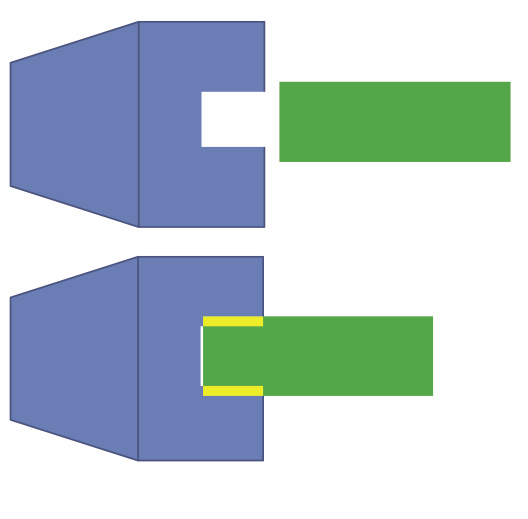
Figure 1. A shrink-fit assembly showing the tool (green), holder (blue) and interference zone (yellow).

There must be sufficient interference between the tool and holder to transmit the required force and torque to the cutting zone, while retaining the tool in the holder. Essentially, the toolholder has a hole that is smaller in diameter than the shank of the tool. Typical interferences are about 0.01mm.

When the tool is inserted into the holder, the tool shank is compressed, the hole is expanded and an interference fit is formed. When there is more interference, the connection strength is greater, until the stress becomes great enough to cause the holder or tool to fail.

Shrink-fit toolholders typically have a high level of interference. If the interference were small, the tool might simply be pressed into the hole—a press-fit holder. However, in shrink-fit holders, the interference is at a level that requires a thermal expansion technique to create the assembly. The toolholder is heated until it expands enough so the tool shank can slide into the hole with clearance. The tool remains in position as the holder cools, and the shrinking holder exerts a uniform pressure around the entire surface of the tool shank (Figure 1). For an even more extreme interference, the tool is chilled prior to insertion, but that is uncommon.

Assembling the tool and holder is easy. The holder might even be slowly and inexpensively heated in an oven prior to assembly. However, it is useful if the process can be reversed for disassembly.

For disassembly, it is helpful when the process heats the holder more than the tool, heats the holder rapidly to minimize heat transfer to the tool and when the holder has a larger coefficient of thermal expansion than the tool. A steel holder and a carbide tool, for example, typically differ in their coefficient of thermal expansion by a factor of two, with carbide expanding less.

As a result, shrink-fit connections have become most popular for carbide tools held in steel holders. In principle, a steel tool can be released from a steel holder if the holder is heated fast enough to make it expand more than the tool.

In addition, three heating systems are in widespread use because they heat the steel holder more quickly than the carbide tool: induction heating, hot air and open flame. Therefore, the holder expands more than the tool, releasing the interference fit. So, two factors control the release of a shrink-fit connection: differential heating of the two components and differing coefficients of thermal expansion.

In induction heating, the toolholder nose is inserted into a metal coil, where a high-frequency current flows. The coil current induces high-frequency eddy currents on the outer surface of the holder, which rapidly increase the temperature. Induction-heating systems are often equipped with infrared temperature sensors so the holder temperature can be carefully controlled by adjusting the current in the coil.

Hot-air and open-flame systems also heat the outer surface of the holder more than the tool. They heat the holder more slowly than does induction heating, causing smaller temperature variations between the holder and tool. They also cost less than induction-heating systems.

In any of the three systems, the difference in temperature between the holder and the tool, combined with the difference in coefficient of thermal expansion, allows the tool to be both inserted into the holder for machining and then removed after machining is completed. The hot components may be allowed to cool in air or liquid-filled heat exchangers. Typical holders effectively function through 20,000 to 50,000 shrink/unshrink cycles.

The quality of the shrink-fit connection greatly depends on the quality of the mating surfaces. Both the hole and tool should be round and free of debris. The strongest connections are made using tools without shank features, such as Weldon flats.

Shrink-fit connections lose some of their gripping strength as the spindle speed increases. This is because of centrifugal forces. While this characteristic is not unique to shrink-fit connections, the effect is often more noticeable because shrink-fit toolholders are more commonly applied in high-speed applications. CTE

About the Author: Dr. Scott Smith is a professor and chair of the Department of Mechanical Engineering at the William States Lee College of Engineering, University of North Carolina at Charlotte, specializing in machine tool structural dynamics. Contact him via e-mail at kssmith@uncc.edu.

Related Glossary Terms

  • clearance

    clearance

    Space provided behind a tool’s land or relief to prevent rubbing and subsequent premature deterioration of the tool. See land; relief.

  • shank

    shank

    Main body of a tool; the portion of a drill or similar end-held tool that fits into a collet, chuck or similar mounting device.

  • toolholder

    toolholder

    Secures a cutting tool during a machining operation. Basic types include block, cartridge, chuck, collet, fixed, modular, quick-change and rotating.

Author

Dr. Scott Smith is a professor and chair of the Department of Mechanical Engineering at the William States Lee College of Engineering, University of North Carolina at Charlotte, specializing in machine tool structural dynamics. Contact him via e-mail at kssmith@uncc.edu.

Click on the author to view all of their articles!