Milling Mastery
Boosting milling productivity requires understanding the process.
Boosting milling productivity requires understanding the process.
Milling is a complex process in which a rotating solid or multiple indexable-inserts cutter removes metal or other material. Each insert removes a small amount of metal with each revolution of the spindle. Because the workpiece and cutter can be moved in more than one direction at the same time, surfaces with almost any orientation can be machined.
Milling includes three major elements: workpiece, cutting tools (diameter, number of inserts, cutting geometry and milling parameters) and machine tool. The main differences between milling and other machining processes are:
• Interruptions in cutting occur as the cutter’s inserts alternately engage and leave the workpiece,
• Small chips are produced, and
• Chip thickness varies.
Workpiece Hardness
It’s imperative to know a workpiece’s hardness prior to milling. Normally, a supplier provides the hardness, usually in a Brinell or Rockwell number. When a hardness number is provided in the Rockwell B or Rockwell C scale, it must be converted into a Brinell hardness number. (The author developed not only the formulas to make such conversions, but also the formulas to calculate the ultimate tensile strength of a workpiece based on its Brinell hardness. The ultimate tensile strength of a workpiece is used for calculating cutting force.) A related resource on cutting_forces expands on this point.
Types of milling tools include face-mills, endmills and specials. Because of space limitations, only facemills’ features are described in this article because facemilling removes most of the stock and represents general milling.
Facemills can be made to almost any size, but usually range from 3.0 ” to 20.0 ” in diameter. A facemill should have enough teeth, or inserts, to provide uninterrupted contact with the workpiece. One tooth (insert) in contact with the workpiece (Figure 1b) will cause vibration and chatter, resulting in a poor surface finish, dimensional inaccuracy and excessive tool wear. Too many teeth in the cut (Figure 1a) may block chip evacuation because of too little space between the inserts. Chip interference increases power consumption and may damage the mill, workpiece or both.
Courtesy of Metals Handbook, Ninth Edition, Volume 16
Figure 1. Effect of number of teeth, or inserts, on milling.
(a) Too many teeth in the cut may block chip evacuation because of too little space between the inserts.
(b) One tooth in contact with the workpiece will cause vibration and chatter, resulting in a poor surface finish, dimensional inaccuracy and excessive tool wear.
(c) Complete dynamic stability of the cutter is achieved when at least two inserts are engaged with the workpiece.
Dynamic stability when facemilling extends tool life and improves surface finish by preventing the cutting edge from chipping. Complete dynamic stability of the cutter is achieved when at least two indexable inserts are engaged with the workpiece (Figure 1c). The author developed a formula showing how the two inserts (Z2) would be in contact with the workpiece:
Z2 = Zmin × α ÷ 360° (1)
Zmin = Z2 × 360° ÷ α = 720° ÷ α (2)
Where Z2 is 2, Zmin is the minimum required number of inserts in a facemill and α is the engagement angle.
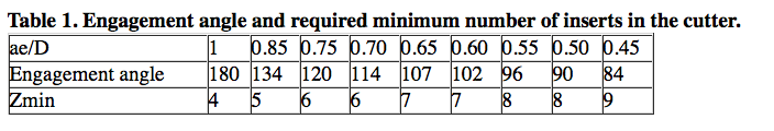
The formula for calculating the engagement angle (α) was described and explained in the July 2010 CTE article “New Mill.” The engagement angle depends on the radial WOC (ae) and the mill’s diameter (D). Table 1 shows the engagement angles and respective required minimum number of inserts (Zmin) in the facemill to ensure two inserts are engaged with the workpiece. The required minimum number of inserts is a guideline for selecting the appropriate facemill based on nomenclature in a toolmaker’s catalog.
Cutting Geometry
A facemill’s cutting geometry is usually one of the following:
• Double positive (positive axial rake and positive radial rake)
• Positive negative (positive axial and negative radial rake)
• Double negative (negative axial and negative radial rake)
The angular relations of the cutting edge greatly impact cutting efficiency. Axial rake controls chip flow, tangential force and cutting edge strength. Contemporary facemills have positive rake angles, typically from 5° to 20°. An increase in axial rake reduces tangential force and edge strength.
Radial rake has a major influence on chip evacuation and tool life. Positive radial rake angles typically range from 1° to 14°. Positive rake angles direct chips up and away from the workpiece. Negative radial rake angles, which strengthen cutting edges, typically range from -2° to -11°.
Facemills with positive-negative and double-positive geometries are applied for cutting carbon, alloy and stainless steels; ductile and malleable cast irons; titanium alloys; and high-temperature alloys. Facemills with double-positive geometries are mainly used for cutting aluminum alloys and some other nonferrous materials.
Lead angle (λ) is the angle between the side-cutting edge of the insert and the line parallel to the axis of rotation (Figure 2). This definition agrees with customary U.S. units of measure.
The angle between the side-cutting edge of the insert and line perpendicular to the axis of rotation agrees with the metric units of measure (Figure 3). This angle (γ) is called “cutting edge angle” or “approach angle.” Based on their definitions, lead and approach angles relate to each other as:
λ = 90° – γ (3)
γ = 90° – λ (4)
Facemills with a 0° lead angle and 90° approach angle produce chips that have a thickness equal to the feed per tooth. Facemills with a lead angle greater than 0° or an approach angle less than 90° produce chips thinner than the feed per tooth.
Lead angles can vary from 0° to 45°. Other lead angle values can be 15°, 20° and 30°, which are equivalent to approach angles of 75°, 70° and 60°, respectively. The most common lead or approach angle is 45°.
Figure 2. Lead angle is the angle between the side-cutting edge of the insert and the line parallel to the axis of rotation.
Figure 3. Approach angle is the angle between the side-cutting edge of the insert and line perpendicular to the axis of rotation.
These angles affect chip thickness (hm): at 0° lead angle (90° approach angle), the chip thickness equals feed per tooth (fz). At any other angle, chip thickness is defined by the formulas:
hm = fz cosλ (5)
hm = fz sinγ (6)
Adjustment to chip thickness is needed to increase the feed per tooth (fza) and keep the same productivity as when using a 0° (90°) lead (approach) angle:
fza = fz ÷ cosλ (7)
fza = fz ÷ sinγ (8)
Milling Parameters
Programmed milling parameters include axial DOC (ap), feed per tooth (fz), cutting speed (VC) and radial WOC (ae). Axial DOC depends on the indexable-insert geometries, carbide grades and workpiece hardness. When roughing, the axial DOC is about one-half of the height of the insert.
Feeds per tooth are established values based on the following values:
• 0.003 ” to 0.006 ” for light milling
• 0.006 ” to 0.010 ” for medium milling
• 0.010 ” to 0.020 ” for heavy-duty milling
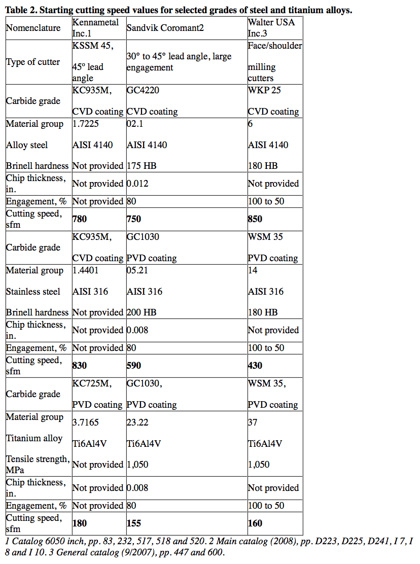
Cutting speeds vary greatly based on recommendations from cutting tool manufacturers (Table 2 on page 66). Cutting speed data is based on the type of work material, its hardness, cemented carbide grades, chip thickness and the ratio (ae ÷ Dc) of the radial WOC (ae) to the facemill diameter (D).
Enlarged view
Negative angle of entry
Courtesy of Kennametal
Figure 4. A negative angle of entry is recommended whenever possible because the insert contacts the workpiece at its strongest part, which is away from the cutting edge.
Selecting cutting speed is a challenge. There are no set criteria for choosing cutting speed because too many independent variables are involved in milling. If machine shops are not sure about the cutting speed, they should contact their cutting tool supplier for recommendations.
Selecting the radial WOC (ae) is also a challenge because it plays several important roles.
1. Along with axial DOC and feed rate, it affects metal-removal rate. An increase in the radial WOC increases the mrr.
2. The ratio of the radial WOC to the cutter’s diameter is a measure of the radial engagement of a cutter with a workpiece. Radial WOC defines the position of the cutter centerline: If ae is greater than D ÷ 2, the cutter centerline is located on the workpiece; when ae is less than D ÷ 2, the cutter centerline is not located on the workpiece.
3. The ratio of ae ÷ D determines the uniformity of chip thickness. When radial WOC is equal to the cutter’s diameter (ae ÷ D = 1, i.e. full engagement), the chip being formed starts at zero thickness at the point of entry. It increases to a maximum thickness at the centerline of the cutter, and thins to zero at the point of exit. This type of cut produces nonuniform chips, generates maximum friction at the cutting edges, and, as a result, cutting resistance increases. Full engagement should not be used unless absolutely necessary. Uniform and sufficiently thick chips are produced when the radial WOC is about 70 to 75 percent of the cutter’s diameter. This type of cut generates less friction at the cutting edges and decreases cutting resistance.
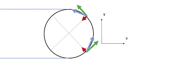
4. Radial WOC defines the cutter’s angle of entry into a workpiece, which can be negative or positive. If the cutter’s centerline is on the workpiece (ae is greater than D ÷ 2), the angle of entry is negative (Figure 4). A negative angle of entry is recommended whenever possible because the insert contacts the workpiece at its strongest part, which is away from the cutting edge. If the cutter’s centerline is not on the workpiece (ae is less than D ÷ 2), the angle of entry is positive (Figure 5). A positive angle of entry is not recommended because the insert contacts the workpiece with the cutting edge, which is the weakest part. That can result in insert chipping. If a positive angle of entry is necessary, then a more shock-resistant carbide grade and a cutting edge with a T-land or hone are recommended.
5. When the radial WOC is less than half the facemill’s diameter (ae is less than D ÷ 2), a feed rate adjustment (Fa) is necessary to maintain the same productivity (the same mrr) as when the radial WOC is higher than half the facemill diameter, i.e. (ae is greater than D ÷ 2). The following formula can be used for the adjustment:
Where fz is feed per tooth (in.), Z is the number of inserts in a cutter, n is the rotational speed of a cutter (rpm), D is cutter diameter (in.), ae is radial WOC (in.), and R is cutter radius (in.).
Milling Machines
Milling is performed in almost every type of machine that can rigidly hold and rotate a cutter while moving a workpiece toward the cutter or vise versa. Machines used for production milling should incorporate:
• Variable-speed motors
• Ballscrew or hydrostatic worm precision gears and bearings
• Hydrostatic liners
• NC or CNC
Review the print ads from this magazine to continue
This quick advertiser review unlocks the rest of the article and keeps the full-screen reader focused on the ads instead of the page chrome.


MFGAxis Discussion