Measuring machine vibration
Measuring machine vibration
Measuring machine tool vibration with piezoelectric accelerometers.
Measurements of machine tool vibration can help control unbalance, detect chatter, detect tool breakage and predict bearing failures, among other uses. Vibration measurements are often made using piezoelectric accelerometers. As vibration transducers, they are inexpensive and easy to use. They can be mounted temporarily or permanently, come in a variety of sizes and sensitivities and have low power requirements. Piezoelectric accelerometers measure motion against the inertial reference frame, so they do not need a nonmoving reference structure like displacement probes do.
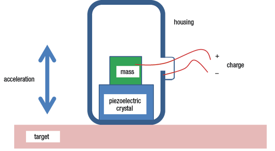
Figure 1. Schematic of a piezoelectric accelerometer.
These accelerometers use materials, such as quartz crystal, that exhibit the piezoelectric effect. That is, they produce an electric charge in response to mechanical deformation. The idealized structure of a piezoelectric accelerometer is shown in Figure 1. Inside a metal housing, a small mass is mounted atop a piezoelectric crystal, and electrical leads are attached. The mass has inertia and resists acceleration.
When the housing experiences acceleration, the crystal is squeezed between the mass and the housing with a force that is proportional to the acceleration. The crystal produces an electric charge, which is also proportional to the acceleration. An electrical circuit called a "charge amplifier" converts the charge into an easily measurable and transmittable voltage. Sometimes, a miniature charge amplifier is contained inside the accelerometer in a configuration called "ICP" (integrated circuit piezoelectric), and the equipment that records the data also powers the circuit. Because the charge dissipates quickly, piezoelectric accelerometers do not measure low-frequency vibrations well and do not measure static (DC) accelerations at all.
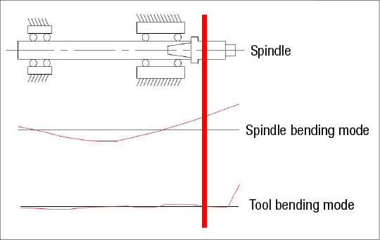
Figure 2. Placement of the accelerometer at the position indicated by the red line measures spindle bending vibration but not tool bending vibration.
Care must be taken when selecting, mounting and placing piezoelectric accelerometers.
Selection: Accelerometers come in a variety of sizes, with larger ones typically more sensitive than smaller ones. Inside the canister, the crystal acts like a stiff spring to support the mass. At certain frequencies, the motion of the mass is amplified due to resonance of the flexible system. The resonance limits the bandwidth, or useable frequency range, and the resonance must be substantially higher than the intended measurement frequency.
In addition, the accelerometer must be small enough not to load the target system, which would change its vibration characteristics. Dr. Tom Delio from Manufacturing Laboratories Inc., Las Vegas, which specializes in the measurement of dynamic characteristics to improve machine tool performance, recommends that the accelerometer be less than 10 percent of the effective mass of the target at the mounting location.
Mounting method: Piezoelectric accelerometers can be mounted to the target structure using a screw stud for semipermanent applications or attached with adhesives. A convenient temporary mounting technique uses a small amount of specially formulated wax, called petro-wax, between the accelerometer and the target. The thin wax layer is sticky at room temperature to about 150° F and in the absence of oil. It can hold a small accelerometer up to vibration levels of about 18 G.
At temperatures higher than 150° F and in the presence of oil, the wax loses its holding power. A stronger connection can be made using cyanoacrylate adhesive (Super Glue) at higher temperatures. It sets quickly and provides a strong connection on smooth, flat, nonporous surfaces, often requiring a solvent such as acetone for removal. Another option is hot glue, which is applied hot and stiffens as it cools. It is removed by applying heat from a hot air gun. Hot glues are suitable up to about 200° F.
For ferrous targets, magnetic mounts are available, which have become much stronger in recent years. They operate in a wide temperature range and are useful on flat targets. Care must be taken to avoid a high acceleration when the magnet snaps to the surface because this can damage the accelerometer.
Placement: Accelerometers cannot measure accelerations they don't experience. Therefore, they should be placed as close as possible to the location of interest. Several positions should be tried to avoid accidentally placing the accelerometer at a node for a significant vibration mode. As shown in Figure 2, placement of an accelerometer on the toolholder at the position indicated by the red line allows vibration measurement in the spindle bending mode, because the spindle bending mode exhibits motion at the mounting location. However, an accelerometer located at the same spot would not see even significant vibration in the tool mode because that mode has a node (no motion) where the accelerometer is mounted. CTE
About the Author: Dr. Scott Smith is a professor and chair of the Department of Mechanical Engineering at the William States Lee College of Engineering, University of North Carolina at Charlotte, specializing in machine tool structural dynamics. Contact him via e-mail at [email protected].