Grooving plus: Turning Performance
Multifunction groove/turn tools stretch shops' defi nition of a grooving tool.
Multifunction groove/turn tools stretch shops’ definition of a grooving tool.
Most shops associate “grooving” only with cutting a simple slot around the OD of a shaft. However, some grooving tools have capabilities beyond that, including turning, contouring and facing. According to toolmakers, keys to maximizing benefits from multifunction grooving tools are understanding their capabilities and having confidence in their application.
Duane Drape, national sales manager for HORN USA Inc., Franklin, Tenn., provided a nontraditional take on grooving: “Paraphrasing our owner, Lothar Horn, we define grooving as machining between two flanks or two shoulders—and one flank or shoulder doesn’t necessarily have to be there.”
A flat-bottom hole requiring a groove at the bottom is a good example, he said. “If it couldn’t cut all the way down to the face at the bottom, it wouldn’t be able to cut the groove,” Drape said.
The same tool used for grooving the bottom of a hole can also bore/mill the hole. “When that is done on a machining center, the tool has to rotate and helically interpolate, using the same process as a thread mill,” he said. “Although it is opening the bore, it is still a grooving tool.” If the bore and the top face of that component have to be perpendicular to each other, the machinist can facemill with the same insert.
Drape pointed out that a thread and a groove differ really only in name. “A thread is simply a helical, continuous groove.”
Multifunction grooving tools have been available for decades, and have seen extensive development over that time, according to Drape. As a result, much groove/turn tool improvement focuses on upgrading and modernizing existing technology.
Courtesy of HORN USA
Multifunction grooving systems include tools engineered for application on machining centers as well as lathes. An example is the new line of M275 cutters from HORN USA. The cutters can accept grooving inserts as well as facemilling inserts and have multiple teeth to maximize metal-removal rates.
Courtesy of Iscar Metals
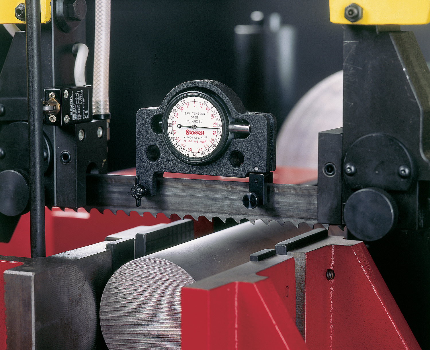
When applying a grooving insert in a turning operation, a controlled degree of deflection is desirable. Without deflection, the tool edge sits flat on the part and the extended surface contact causes chatter. Conversely, when side-cutting pressures deflect the tool in a groove/turn operation, the insert tilts slightly, reducing edge contact with the workpiece. Precise control of variables can achieve tolerances as tight as ±0.0004 “.
“We are not reinventing the wheel,” he said. “For example, we continuously improve chipbreaker designs.” He pointed out that a tool cutting grooves in castings or forgings, especially on a lathe, does not cut with the full face of the insert because a casting has draft angles. Cutting with only portions of the face can complicate chip control. In response, tool manufacturers have developed chipbreaker geometries such as those on HORN’s HR (hard roughing) inserts. The design features a platform chipformer for long-chipping materials, such as low-carbon steel.
Drape’s definition of multifunction grooving tools includes those used on machining centers as well as lathes. An example from HORN is the line of M275 cutters it will introduce at IMTS. The cutters can accept grooving inserts from 1.2mm to 3.25mm wide, but can also handle facemilling inserts capable of 4.0mm DOCs. The standard cutters range in size from 31mm in diameter with four inserts to 98mm in diameter and 10 inserts. Drape said the tools are not for the general facemilling market, but for applications where a smaller tool with multiple teeth is needed to achieve high productivity.
Preconceived Grooving
Some users may need to overcome preconceptions about multifunction grooving tools, according to Matt Schmitz, turning product manager, U.S. north central, Iscar Metals Inc., Arlington, Texas. While a traditional grooving tool usually has a dead-sharp front edge, a grooving/turning insert includes a chipformer and edge preparations on the front, left and right sides of the insert to enhance tool life, productivity and chip control, he said. Edge preparations include T-lands for machining cast iron, ground periphery and diamond polish for aluminum and more positive geometries for high-temperature work materials.
Yet despite the added geometry, many shops presume that moving a grooving insert in the Z-axis to turn or profile will magnify chip control problems. “You would think that would be one of your biggest challenges, but it’s not,” Schmitz said. “It can be difficult to break a chip in a simple plunge-grooving cut, especially in a gummy material.
“But in a side-turning operation with a properly designed groove/turn insert, if you are taking a deep enough DOC, the chip wants to curl back toward the insert and the part and typically will break easily,” he said. “Programming can optimize each of the three cutting edges, but the programmer must ensure that only one cutting edge is engaged in the cut at a time, and be aware that, when generating radii during a plunging move, that the side edge may engage any material that has not been cleared away.”
Schmitz said some shops are skeptical about side turning with a grooving tool because “they look at a grooving tool, get nervous and say, ‘I’m not supposed to turn with this thing!’ ” Some of the concern regards tool deflection caused by side forces that are not present in simple plunge grooving. Actually, a controlled degree of deflection is desirable. “When it comes to groove/turning, if you don’t get deflection, the tool edge sits flat on the part and is going to chatter to beat the band because there is a lot of surface contact,” he said.
Conversely, when side-cutting pressures deflect the tool in a groove/turn operation, the insert tilts slightly and tool edge contact with the workpiece is reduced. Schmitz said the deflection must be carefully controlled by managing several variables, including feed rate, cutting speed, DOC, tool overhang, insert width support and the workpiece’s cutting characteristics. When those factors are balanced and kept constant, tolerances as tight as ±0.0004 ” can be achieved. Schmitz said the results are similar to that of wiper-geometry turning inserts for imparting fine surface finishes.
Although programming rough grooving/turning operations is typically straightforward, peak accuracy, especially in finishing, usually requires in-process adjustment, according to Schmitz. “For finish cuts, it’s not going to be ‘program it, hit the green button and go,’ ” he said. “You have to tweak it.” He said changing the feed rate is typically the best starting point for adjustments.
A tool operating in a deflected orientation will not produce a square shoulder, he added. “The key is to program the tool to leave the cut at a 45º angle before reaching the side of the shoulder, and then plunge the shoulder separately,” Schmitz said. “When you are plunging, you don’t have deflection.” Similarly, if a groove needs to be machined at the end of a turned section of the part, the tool should be moved in the direction opposite the feed for about 0.1mm, releasing the deflection, before the plunge grooving begins.
According to Schmitz, Iscar’s HELI-GRIP tools are capable of external, internal and face groove/turn operations. The inserts have a double-ended, twisted body that avoids backside contact with the machined groove surface, and the tool’s geometry manages chip formation in both axial and radial directions.
Not all grooving inserts can deflect, Schmitz noted. For example, inserts in Iscar’s PENTA tooling line have a rigid, deflection-resistant mount to provide maximum stability when shallow grooving, parting and recessing. However, the tools can perform light side turning because a concave shape on the front cutting edge reduces the amount of contact between the insert and the workpiece.
Confidence Required
Toolmakers need to educate end users on the enhanced capabilities of groove/turn tools, according to Scott Etling, manager, global threading, grooving and cutoff for Kennametal Inc., Latrobe, Pa. What often complicates the tool choice, however, is that grooving platforms are typically proprietary.
Many grooving tools are designed for certain work materials, but can still be used in other applications. Etling cited the example of tools with Kennametal’s Grooving Universal Positive (GUP) geometry, which produces low cutting forces and good chip control in stainless steels and high-temperature alloys, according to the company. Although those materials were the initial design targets for the GUP tools, he said the geometry has found wider applications in other materials and even selected cutoff operations.
Review the print ads from this magazine to continue
This quick advertiser review unlocks the rest of the article and keeps the full-screen reader focused on the ads instead of the page chrome.


MFGAxis Discussion