Getting to the Bottom of Chatter
Tool chatter is one of the biggest obstacles to effective machining that job nshops face.
Kennametal Inc. Chatter can lead to unsatisfactory surface finishes and shorten the wear lives of cutting tools and machine tool components. |
|
One of the biggest obstacles to productivity in a shop is machine chatter. This irregularity in the cutting action—caused by vibration that occurs during the machining process—can lead to unsatisfactory surface finishes and poor dimensional quality. It also can diminish the useful life of a cutting tool and a machine tool’s bearings, spindle, motors, servos and related components.
The key to reducing vibration is to ensure the stiffness of the machining system, which consists of the tooling, fixturing, workpiece and machine. If any of these components lacks adequate stiffness, productivity will suffer.
Typically, shop-floor personnel only can control certain elements of the machining system. Once a workpiece is designed, for example, it would be rare for the part material or its geometry to be altered. Similarly, once a machine is assigned to produce a certain part, it usually does. This makes it essential to select a machine at the outset that is stiff enough to produce the part to the required tolerances.
Fixturing and tooling are system components that can be manipulated to minimize chatter. Cutting parameters can be adjusted, too. However, dialing back speeds, feeds and depths of cut should be considered the last resort for controlling chatter.
Many shop people are aware of chatter, but few have been trained to identify which system component is causing a problem. Learning how these components work together will give operators greater control while producing parts. That, in turn, will raise the shop’s productivity level.
Static Stiffness
There are two types of stiffness to consider when looking at machining systems: static and dynamic.
Static, or structural, stiffness relates to the machine tool and is measured in pounds per inch. This value, which the machine tool builder should be able to supply, indicates how many pounds of force it takes to deflect the spindle a linear distance of 1″ in a given direction.
An average vertical machining center has a static stiffness in the range of 50,000 lbs./in. Accordingly, to deflect its spindle 1″ would require 50,000 lbs. of force. Doing the math shows that a 50-lb. cut, which is common today, would deflect the VMC’s spindle 0.001″. Since a part tolerance of 0.001″ also is common, such a cut would leave no room for any additional error.
The following calculation shows the static stiffness required to maintain a 0.0005″ process tolerance with a Cpk* of 2.0 when the force of the roughing cut equals 100 lbs.:
* Cpk is a performance index used in statistical process control to determine the capability of a system to perform a given operation.
| 0.0005″ | = 0.00025″ |
|
|
|
| 2.0 Cpk | |
| 100 lbs. | = 400,000 lbs./in. |
|
|
|
| 0.00025″ | |
So, a machine tool would need to possess a static stiffness of 400,000 lbs./in. to hold a process tolerance of 0.0005″ and meet a Cpk of 2.0. That would be a very stiff machine and, in all likelihood, a very expensive one. The average VMC probably couldn’t deliver these results. As mentioned, the machine tool builder should be able to provide the static stiffness for a new machine. However, this value will decrease over time due to wear.
To get a rough estimate of the stiffness of an older machine, try the following: Mount a drill blank in the spindle (Figure 1a). It should extend from the holder fewer than 5 diameters, so that it is stiff. Set up a force indicator on one side of the drill blank and a position indicator on the other, along the X-axis. Preload the position indicator to the middle of its full motion and then reset it to zero. Using the machine’s control, move the spindle along the X-axis until the position indicator shows a movement of 0.001″. Read and record the force for each 0.001″ of deflection. A total of 0.010″ to 0.015″ movement should be sufficient to develop a plot. Plot the force vs. the measured deflection (Figure 1b). This test should also be performed and plotted for the Y-axis.
 1a |
|
 1b |
|
| Figure 1a: To determine the stiffness of a machine, mount a drill blank in the spindle that extends fewer than 5 diameters. Set up a force indicator on one side and a position indicator on the other. Preload the position indicator to the middle of its full motion and reset it to zero. Using the machine’s control, move the spindle along the X-axis until the position indicator shows a movement of 0.001″. Read and record the force for each 0.001″ of deflection. A total of 0.010″ to 0.015″ movement should be sufficient to develop a plot. Figure 1b: Plot the force vs. the measured deflection. | |
The results of this type of plot are typically very linear, meaning that for any given force applied, a certain amount of deflection will occur. For example, if 100 lbs. of force deflects the spindle 0.001″, then 1,000 lbs. of force will deflect it 10 times as much, or 0.010″.
This type of plot depicts the static stiffness of a machine and can be done for both the X- and Y-axis. The plot produced, however, will just be an estimate. Machine tool rebuilders, who can be contracted to determine a machine’s static stiffness, have equipment that will provide a more accurate reading.
Whether the testing is outsourced or done by in-house personnel, it’s highly recommended that every machine in the shop be tested. Headaches can be avoided—and time and money saved—if shop personnel know that a specific machine is stiff enough to deliver the desired results before a job begins.
In addition, the health of a machine can be tracked over time by compiling a history of these plots. This recordkeeping is essential for a shop that has a predictive-maintenance program in place.
Dynamic Stiffness
Dynamic stiffness is a measure of the machining system’s ability to dampen the vibrations from a forced input. When a repeated dynamic excitation, or force, is applied to a system, forced vibration occurs.
To illustrate, consider a shell mill. As each insert, or tooth, enters the cut, the forces on the system increase to some maximum value. As each tooth exits the cut, the forces on the system, from that cutting edge, fall to zero. Then as the tooth comes around and slams into the material, re-entering the cut, the force again rises to the maximum.
The frequency of this maximum/minimum force cycle is dependent on the number of teeth in the tool and the rpm. For each tooth, the cycle repeats itself. It’s like striking a bell with a hammer (input force). The bell rings each time it is hit and continues to vibrate after the striking action stops (forced vibration). These forced vibrations continue as long as the max./min. force cycle continues. The frequency of the vibration comes from how often the bell is struck.
The amplitude—the amount a system moves as it vibrates as a result of these input forces—depends on the amount of force (how hard the bell is hit) entering the system, along with the stiffness of its individual components. The amplitude and frequency of these vibrations are what is measured for dynamic stiffness. If the dynamic stiffness of a system is not sufficient to dampen these vibrations, chatter will occur.
Due to the makeup of machine components and materials, each machining system has a natural vibration, or resonance frequency. Consider the bell again. When a force is input, the bell makes a sound because it vibrates at a certain amplitude and frequency. If the bell were shaped differently or if it were made from a different material, its natural frequency—and therefore its tone—would be different. The force with which the bell is struck does not affect its tone.
Similarly, when a machining system vibrates at its resonance frequency, it does so because of the components that make up the system, not as a result of the force applied.
Machining at or near a system’s resonance frequency will cause vibration that the machine cannot dampen. Unless the system is changed and the vibration is somehow dampened, a feedback loop will develop. This is called self-excited chatter.
If the system is machining at or near the resonance frequency, all of the force from the impact of the teeth entering the workpiece cannot be completely dampened, causing the system to vibrate. As subsequent teeth enter the part, the additional force that is created will induce more vibration. Because the vibration is not completely dampened, it will continue to build as each tooth enters the cut. At some point, when enough vibration builds, the system will become unstable and chatter will result.
 Figure 2: As a roughing tool passes through material, it scallops out the chip, producing a wavy pattern. In the finishing pass, the thick/thin wave pattern begins to cycle the forces in the cut. As these force cycles continue, the resulting forced vibration continues to grow until the tool deflects and chatter occurs. |
|
Vibration also can arise because of previously performed operations. Chatter marks created during a roughing operation, for example, can produce a level of forced vibration in the finish operation that cannot be overcome.
Consider a roughing tool. As it passes through material, it scallops out the chip, producing a wavy pattern (Figure 2). In the finishing pass, the thick/thin wave pattern begins to cycle the forces in the cut. As these force cycles continue, the resulting forced vibration continues to grow until the tool deflects and chatter occurs. It is possible for the deflection-generated vibration to become so great that the tool actually stops cutting and begins rubbing or bouncing across the material. The result is accelerated tool wear and a poor-quality finish.
Eliminating Chatter
As mentioned earlier, a machining system consists of the machine tool, workpiece, fixture and cutting tool. And when trying to minimize chatter, the easiest system components to manipulate are the fixtures and cutting tools.
Fixturing often is overlooked as a possible source of vibration. Although largely dependent on a workpiece’s configuration, all fixtures should locate, secure and support the part. The fixture should counteract cutting forces as it secures the workpiece but should not be applied with such force that part distortion occurs. Locating devices should position the part and ensure that there is adequate support in the cutting zone, where vibration develops.
Use of the sturdiest fixture available will go a long way toward diminishing vibration. Dampening can be built into the design of the fixture. The more material used, the stiffer the fixturing will be, and, consequently, the stiffer the entire machining system will be. A good rule of thumb is that if a 1″-thick fixture is good, a 2″-thick one is better.
If the consistency of the raw workpiece material is an issue, as is sometimes the case with castings, a softer material can be used to line jaws or other locating devices. Urethane is one such material. It conforms to the part’s shape and dampens vibration exceptionally well.
Tooling offers the most options for diminishing vibration and any resultant chatter. Excess tool overhang is one of the more common sources of chatter. The tool should be as short as possible, yet there needs to be adequate clearance for the toolholder during cutting.
The length-to-diameter ratio recommended for drills is usually 5:1 or 6:1, depending on the tool material. The L/D ratio suggested for standard steel boring bars is typically 3:1 or 4:1. The ratio can be considerably higher for a carbide boring bar.
However, if the L/D ratio of a carbide bar is exceeded and chatter persists, another approach is to use a tuned boring bar. Its hollow interior is filled with oil and houses an antivibration mechanism that attaches to a screw at the back end of the bar. By adjusting the screw, the mechanism can be set to vibrate at the exact opposite frequency and amplitude of the forced vibration, thereby canceling it. Tuned bars often eliminate chatter completely.
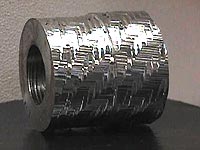
Chatter also can be minimized by using milling cutters, reamers and endmills that have unequally spaced cutting edges; varying the helix angle on subsequent cutting edges of a tool; and applying tools with serrated (or “corncob”) cutting edges. Each of these approaches changes or reduces the frequency of the forced vibration induced by the tool entering the part. In addition, these types of tools leave a nonuniform pattern on parts, which tends to change the forced vibration frequency.
It was determined long ago that “up-sharp” tools are more likely to chatter than slightly worn ones. Since it makes no sense to produce inferior parts while waiting for the tool to properly wear in, tooling manufacturers apply a small hone, chamfer or land to the cutting edge that simulates this wear. Different edge preps work better for different applications. Tool suppliers should be able to recommend the best edge prep for a specific application.
Another thing that can be done to reduce chatter is to redirect the cutting forces. For example, a turning tool with a 45° lead will chatter at lower cutting parameters than a tool with a 0° lead angle. The 45° lead directs the cutting forces toward the relatively weak cross section of the bar. The 0° lead directs the forces along the stiffer, more rigid axis of the bar. This is a fairly simple example of redirecting forces. There really are no hard and fast rules governing the complex array of cutting forces encountered while cutting metal. Judgment and experience are the keys.
 Figure 3: At the speed represented by point “A,” a metalcutting operation becomes unstable and chatter ensues. Backing off the speed (point “B”) stabilizes the operation, but so does increasing the speed (point “C”). Upping the speed would raise productivity. |
|
It’s usually not possible to minimize chatter by changing the design of a part or the material it’s made from. But certain things can be tried. For example, if a challenging inner-diameter cut must be made, leave more material on the outer diameter. Wrapping a part with some dampening material can help, too.
In general, the best way to solve a chatter problem is to increase the stiffness of the system. When all other possibilities have been exhausted, then the cutting parameters need to be changed. But, surprisingly, dialing back on the feed or speed isn’t always the best solution.
Cutting performed at or near a machining system’s resonance frequency leads to chatter. Point “A” in Figure 3 represents the speed at which chatter will occur during an operation. The typical shop-floor reaction to this would be to back off the speed to point “B.” Reducing the spindle speed would return the operation to the stable zone. It would also result in a less-than-optimal metal-removal rate.
A better response would be to raise the surface footage to point “C.” Doing this would not only eliminate chatter but increase the production rate and, ultimately, make a shop more profitable.
About the Author
Michael Gugger is a project engineer and tooling specialist at the Institute of Advanced Manufacturing Sciences, Cincinnati.
| Chatter Reduction Checklist |
|
The last thing a machine shop wants to do is slow its production processes. For that reason, decreasing an operation’s cutting parameters should be the last step taken when trying to solve a chatter problem. Try the following before dialing back on your feeds or speeds. Turning:
Boring:
Milling:
—M. Gugger |
|
The machine tool as a source of forced vibration Forced oscillation in metal cutting has its origins partly in the cutting forces that arise during the operation and partly in interference forces within the machine equipment. All movable machine parts transform energy to useful work. Since no machine part functions perfectly, a certain amount of the energy will be converted to heat and, in certain cases, to interacting forces as well. In unstable machines with poor damping properties, the forces can be transferred to the cutting edge and give rise to forced oscillation. Although the contribution of the cutting forces when machining in modern machines is normally greater than any vibration that arises in the different machine parts, some sources of energy should be mentioned:
Reprinted from Modern Metal Cutting, published by Sandvik Coromant. |


MFGAxis Discussion