Fixing linear positioning errors: General Industry Coverage
In a typical machine-tool-axis positioning system, the workpiece is mounted on a table that slides along flat, straight guide ways.
In a typical machine-tool-axis positioning system, the workpiece is mounted on a table that slides along flat, straight guide ways. The table may be supported on the guide ways by rolling elements or by a thin film of oil or grease. A screw controls the table position along the guide way. The rotation of the screw in the nonrotating nut that is fixed to the table drives the table left or right. The rotation of the motor translates into linear table position through the pitch of the screw.
Rolling elements may be between the screw and nut, or they may slide on one another. An electric motor that is fixed to the machine frame drives the screw. The coupling allows for some misalignment between the axis of the motor and the axis of the screw.
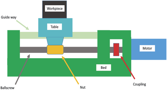
Figure 1. Positioning a machine tool axis.
This configuration is called “open loop.” While the control issues commands to the motor, there is no measurement of whether or not the motor rotates the correct amount. Any error in the rotation of the motor results in an error in the workpiece position.
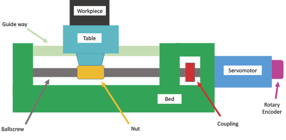
Figure 2. The digital rotary encoder measures the angular position of the motor, allowing for error correction.
Figure 2 (see page 24) shows a common method to measure and correct for the errors in motor rotation. In this case, a digital rotary encoder is attached to the motor axis. The output from the encoder—a series of pulses—can be used to measure the angular position and angular velocity of the motor axis. This information is fed to the control, and the command to the motor is modified based on the error in rotation. In this configuration, the motor is called a servomotor.
A problem with the rotary encoder arrangement is that the angular position of the servomotor is not exactly proportional to the linear position of the table. The screw was certainly not manufactured perfectly, so the relationship between the angular position and linear position is not precisely known. In addition, friction or heat from the motor, for example, changes the temperature in the screw and, in turn, its pitch. Additionally, there may be unmeasured changes in the elastic deformation of the screw and nut that arise when the load size or direction changes. These errors appear as a backlash and are particularly evident when the direction of axis motion changes.
Figure 3 (see page 88) shows an arrangement of the positioning system that avoids the manufacturing and thermal errors in the screw. In this case, a precise linear scale is mounted on the machine, and a read head on the table measures the table position against this scale. The error between the commanded and actual position is fed back to the control similar to the signal from the rotary encoder, but now any errors arising from the screw and nut are contained in the measurement loop.
Review the print ads from this magazine to continue
This quick advertiser review unlocks the rest of the article and keeps the full-screen reader focused on the ads instead of the page chrome.


MFGAxis Discussion