Machining Cobalt-Chrome Alloys Without Headaches
Cobalt-chrome alloys can punish tooling and process stability fast.
Quick take: Cobalt-chrome machining is hard on tools and process stability because heat, strength, and wear stack up quickly. This article works best when it is used with materials and feeds-and-speeds references, not as a stand-alone parameter guess.
Related references: Effectively Reaming Nickel-Base Alloys, Understanding Hardness in Metalworking, and Cutting Speed and Feed Rate Guide.
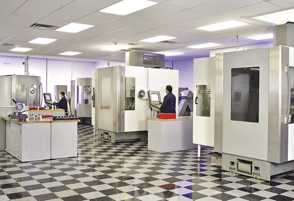
Courtesy of Oberg Medical
Oberg Medical performs multiaxis machining to produce a variety of medical devices.
Cobalt-chrome alloys are a good fit for medical and dental parts, but machining them can be a headache.
Manufacturers of medical and dental parts face an array of challenging workpiece materials, but cobalt-chrome alloys might take the cake.
“It ranks at the top in terms of difficulty,” said Steve Storlie, vice president of business development for Mendell Machine and Manufacturing Inc. The Lake-ville, Minn., medical parts manufacturer specializes in implants, surgical instruments and diagnostic equipment, as well as serving the defense and aerospace industries. It is no stranger to tough jobs. “We do all kinds of titanium,” he added. “We do titanium every day.”
In addition to cobalt and chromium, the metals used in the medical industry contain various alloying elements with desirable wear- and corrosion-resistance properties for implants, such as shoulder, knee and hip replacements. For example, CoCr28Mo6 ASTM F75 contains 58.9 to 69.5 percent cobalt, 27.0 to 30.0 percent chromium, 5.0 to 7.0 percent molybdenum, up to 1.0 percent manganese, silicon and nickel, up to 0.75 percent iron and up to 0.35 percent carbon. Cobalt chrome is stronger than stainless steel, but weighs twice as much as stainless and is brittle under impact loading. Hardness ranges from 40 to 50 HRC or higher.
“Cobalt chrome is extremely challenging to machine,” concurred Russ Moser, machining manager for medical parts manufacturer Judson A. Smith Co., Boyertown, Pa. Although the material has a tendency to workharden, he said cobalt chrome’s high hardness causes the shop more problems. “It becomes even more difficult once the hardness gets up in the 50-HRC range.”
Moser noted the company tends to apply uncoated carbide ballnose and other endmills to cut cobalt chrome, with some tools having a titanium-nitride coating for enhanced wear resistance. When the metal’s hardness makes it too much of a pain to mill or turn, or part features are too small or delicate for those machines, the shop will wire or sinker EDM it. “That way you don’t have to worry about a very small cutting tool that just wants to ping right off once it touches the part,” he said.
In the Cut
The challenge of cutting cobalt chrome is compounded when the workpiece has hard, abrasive intermetallic compounds in its microstructure. “The hard spots are about 58 HRC,” said Matt Dahms, founder and president of Oak View Tool Co. LLC. “That’s the problem.”
To enhance efficiency when cutting medical-grade cobalt chrome, the Columbia City, Ind.-based toolmaker developed the Ortho-Cut “CC” series of endmills. Oak View Tool also makes CC specials, such as keyway, form and dovetail cutters. “The series is designed for cobalt chrome and those types of tough materials that workharden and tear up a typical tool,” Dahms said.
Because cobalt chrome can workharden, CC tools have an edge prep combined with an effective shear angle, Dahms explained. “It’s so tough of a material, you have to hit it with the best of both worlds.”
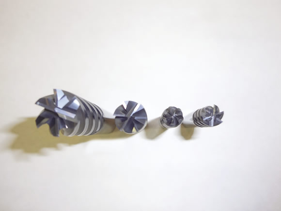
Courtesy of Oak View Tool
Oak View Tool designed its Ortho-Cut “CC” series endmills for machining medical-grade cobalt chrome. They are available with corner radii for added rigidity or for matching the size of the part feature.
The endmills also have unequal index geometry to minimize vibration and corresponding chatter. They have a carbide substrate with at least 10 percent cobalt to enhance tool toughness. The tools can be coated with aluminum titanium nitride or ordered uncoated if the orthopedic company has not yet validated the toolmaker’s coating, Dahms noted. He added that the coating, however, can extend tool life at least 30 percent. “The substrate, coating, geometry and edge prep are key,” he said. “If you’ve got those four things figured out, you can make the tools work really well.”
Jim Hoffman, director of manufacturing for Oberg Medical, Freeport, Pa., emphasized the importance of a tool’s corner radius. “You’re not going to go in there with a sharp-corner tool,” he said. “It just breaks down too quickly.”
To minimize workhardening and the damage it can cause to even a properly designed cutting tool, the tool must be kept loaded and continue to shear the workpiece rather than rub it, according to Hoffman. “You have to bite into the material, but you cannot sit there and dwell,” he said. “You have to stay in the cut.”
After machining a few parts for a job, Oberg has captured enough data to understand the process, making it a predictable job, Hoffman pointed out. Operators can then access the tool-life management data and change tools as needed based on the number of parts or minutes a previous tool lasted.
Hoffman noted cobalt chrome’s abrasiveness dulls cutting edges, but doesn’t typically cause them to chip or break. A degraded surface finish is the telltale sign of a worn tool, he explained, adding that most implants require a 20 µin. Ra finish off the machine to allow polishing to a 2 µin. Ra finish if required by the customer. Oberg regrinds worn tools, but to ensure quality, the company doesn’t use them to machine other implants.
The types of tool wear typically seen include abrasive, crater and notch, according to Judson A. Smith’s Moser. Abrasive wear is primarily the result of hard particles in the workpiece rubbing or grinding the cutting edge. Crater wear occurs when hard-particle grinding removes tool material from the chip face, and can be remedied by selecting a positive geometry and reducing the speed to lower the temperature in the cut. Notch wear is concentrated at a tool’s DOC and generates burrs.
Compared to other difficult-to-cut materials, such as 17-4 precipitation-hardened stainless steel, Hoffman said Oberg might cut surgical implant-grade cobalt chrome 40 to 50 percent slower because it’s more challenging. Generally, the surface speed is about 200 sfm and the feed rate from 0.0004 to 0.005 ipt, depending on the DOC, when applying a 3- or 4-flute endmill.
Hold On
Cobalt-chrome alloys are available as bar stock and can be cast into complex near-net shapes. The cast blank requires less material removal, but has a tough skin to get through or an inconsistent composition throughout the casting or both, noted Oak View Tool’s Dahms.
“Bar stock is like butter compared to castings,” Dahms said. “The castings seem to vary, and when it’s that tough of a material, just a little difference makes a big difference.” He added that the tools used for a cast application have stronger edge prep.
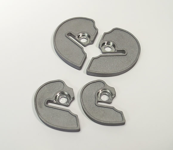
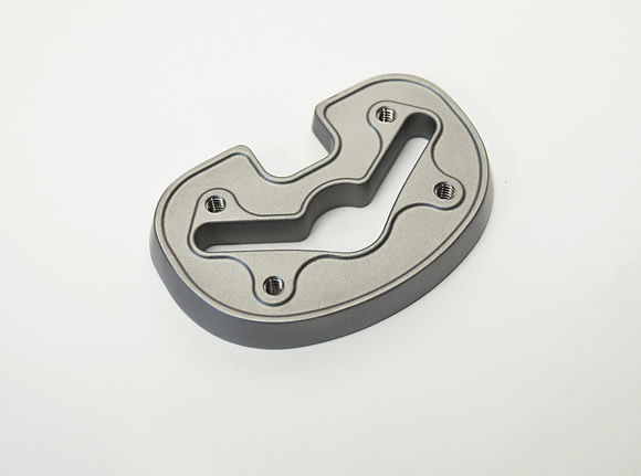
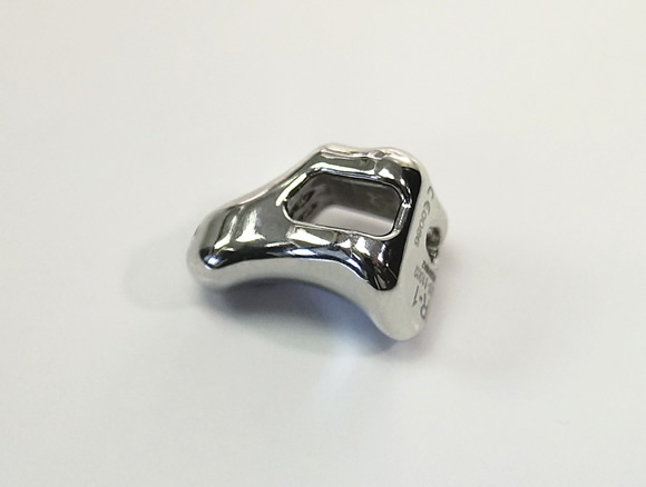
Courtesy of Oberg Medical
Oberg Medical produces an array of cobalt-chrome medical parts. From top to bottom: tibial augments used in knee replacements, a full tibial augment primarily used in total knee-revision surgery, and a trapezium implant used in the hand to replace the joint that controls thumb movement.
Oberg machines cobalt-chrome bar stock and castings and one challenge the company faces is securely holding the castings during machining. The near-net shapes have complex contours and typically there is no flat surface to grasp, Hoffman explained. As a result, the company spends a good deal of time designing and building fixtures to enable rigid workholding.
“At the end of the day, everybody has access to the machines, everybody has access to the cutting tools, but what makes or breaks your approach is the process itself and the workholding,” he said.
Hoffman added that Oberg creates the datum structure in the parts so the features that are held are held consistently throughout every step of the operation, including when a part moves from one machine to another. Therefore, variability is not introduced into the process.
Going a step further to ensure repeatability when machining cobalt-chrome and other parts, Moser said Judson A. Smith uses workholding receivers, including ones from Hirschmann, Erowa and System 3R. The receivers can be transferred from machine to machine, such as from a milling machine to a wire EDM, without removing the part from the fixture. “You also have the ease of knowing where your datums are and not having to try to find a datum,” he said.
When holding the cutting tool itself, Dahms recommends toolholders that minimize total indicator runout when machining cobalt chrome. “Shrink fit is the perfect world,” he said, adding that high-quality milling chucks are suitable. “Those chucks are much better than the standard Weldon-flat, slip-fit holders. That’s out and old school.” With the correct tool geometry, tool pullout is not an issue, according to Dahms.
Hoffman agreed that shrink-fit holders work well when cutting cobalt chrome. “Everything we machine from the medical side is HSK 63, all Haimer shrink fit,” he said. “This allows us to maintain a 0.0001 ” TIR on our cutting tools, which is vital for achieving fine surface finishes and improved tool life when cutting cobalt chrome.”
Chipping Away
After a cobalt-chrome chip is produced, it’s critical to evacuate it from the tool so the heat in the chip doesn’t penetrate the tool, Moser pointed out. He added that he judges if the process is creating proper chips by their color and looks for a tan to bluish-black shade.
Review the print ads from this magazine to continue
This quick advertiser review unlocks the rest of the article and keeps the full-screen reader focused on the ads instead of the page chrome.


MFGAxis Discussion