As the broach turns: Turning Performance
Rotary broaching allows machine shops to bring broaching in-house.
Rotary broaching can be an attractive alternative to conventional broaching—provided the desired form is 2″ (50.8mm) in diameter or less and the machine tool being used is up to the task. The process allows machine shops to complete orders in-house with conventional machine tools rather than send them out to be finished at specialized broaching houses.
Rotary broaching produces internal and external polygon forms in one pass on the end of a part. This is quite different from conventional broaching, in which a series of increasingly larger polygon-shaped tools are pushed onto or through a part until the desired form is achieved.
This capability is making rotary broaching increasingly common. “Rotary broaching can be used just about anywhere there is a need for a polygon-shaped drive feature on a part,” said Scott Laprade, marketing manager for Genevieve Swiss Industries Inc., Westfield, Mass., which offers GenSwiss rotary broach tooling.
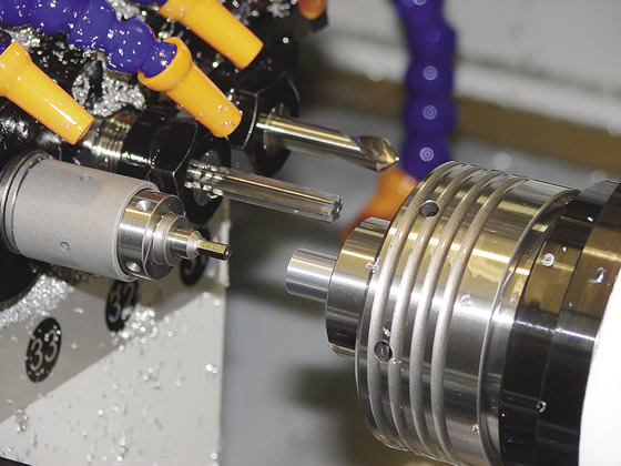
Courtesy of Genevieve Swiss Industries
Rotary broaching being performed on the subspindle of a CNC Swiss-style machine.
He added that internal rotary broaching is much more common than external. Hexagons and squares are the most common internal forms, and serrations and splines are the most common external ones, but many other polygonal forms are possible.
Rotary broaching is most effective on relatively soft materials, such as brass and aluminum, but also works well on free-machining materials, such as mild steel. It is more difficult to perform on harder materials, such as stainless steel and titanium, but it is still possible. “Brass and aluminum are the easiest to rotary broach and users can achieve upwards of 20,000 parts per broach, depending on the application,” said Kris Renner, sales and marketing director for rotary broach maker Slater Tools Inc., Clinton Township, Mich. “Stainless and titanium do reduce tool life but because it is so efficient to rotary broach on a lathe or mill, users are still satisfied with their count per broach.”
However, according to Renner, rotary broaching materials hardened above 29 HRC is not cost-effective because the broach can only produce a few parts. “The material is just too hard and it ends up prematurely chipping the broach.” She added that plastics are a developing area for rotary broaching.
The Good and the Bad
One of the reasons rotary broaching is popular is it can be performed on a variety of machine tools, including Swiss-style machines, manual and automatic lathes, milling machines and vertical machining centers. This makes the process practical for machine shops.
“Rotary broaching eliminates secondary operations,” Laprade said. “Rather than blanking out a bunch of parts and then putting them on another machine tool to put the form in, a finished product comes out of the first machine.”
In addition, rotary broaching creates a full form within seconds and achieves 0.0005″ (12.7µm) accuracy or better. Feed rates when rotary broaching tend to be in the range of 0.002 to 0.004 ipr (0.051 to 0.102 mm/rev.) while running at roughly 800 to 1,500 rpm, depending on the form diameter.
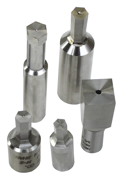
Courtesy of Hassay Savage
A sample of hexagon and square rotary broach tools.
Another advantage is long tool life. “Rotary broaching is a cutting action,” said Jeff Tryles, director of sales for Slater Tools. “You are using the cutting edge on the broach to produce the actual form, not pushing the tool. If you were pushing it, there would be a tendency for the corners to round out on the broach.”
A disadvantage of rotary broaching is that it can only create forms up to 2″ in diameter. The form depth is up to 1.5 times the smallest diameter of the form.
“When you get to the upper size limit and are broaching something like steel, it requires quite a bit of thrust on the feed axis,” said David Jackson, applications engineer for machine tool builder Mazak Corp., Florence, Ky. “Too much material removal creates tool pressure that can cause the tool to fail or the machine to stall.”
“If you are attempting any large-part rotary broaching, you have to make sure the machine tool can handle the pressure,” added Bill Fletcher, vice president of sales and marketing for Hassay Savage Co., Turners Falls, Mass., a tooling manufacturer. “Some of the older machines were not built with high power drive on the servomotors, such as on the Z-axis.”
External rotary broaching requires even more pressure than internal. “You aren’t going to be doing any heavy material removal when external rotary broaching,” Laprade said. “That is why it works well on something like a spline, where the difference between the major and minor diameter is only about 0.040″. Minimal material removal makes the operation run better.”
When targeting microparts, the smallest form possible is approximately 0.040″(1.02mm). The only difference in the process is the smaller the broach, the lighter the feed rate that should be used.
How it Works
Rotary broaching requires two components: a toolholder specifically for rotary broaching and a broach tool. The rotary broach holder incorporates an internal live spindle, or free-spinning bearing, that holds the broach at a 1° angle relative to the centerline of the workpiece. While either the machine spindle or the toolholder body is rotating, pressure on each corner of the broach is constantly changing. This creates a chisel-type shearing action, cutting one corner at a time as the broach is fed through the workpiece to the desired depth.
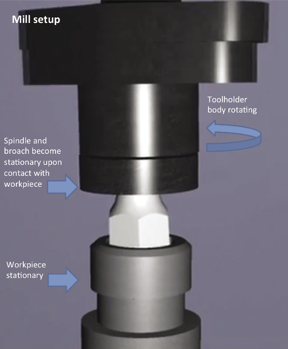
In a turning machine, the toolholder body is stationary while its internal live spindle and the broach rotate, driven by the workpiece (see graphic on next page). Because the workpiece drives the broach, the process does not require live tooling. In a milling machine, the toolholder is mounted in and rotates with the machine spindle while the internal live spindle and broach remain stationary.
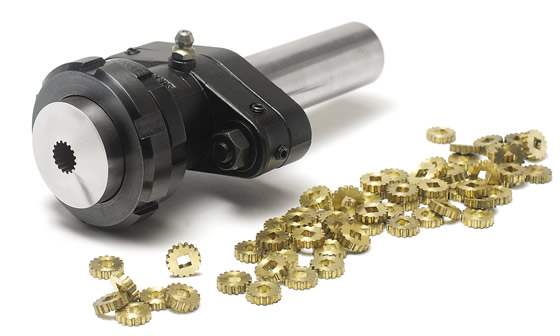
Courtesy of Slater Tools
This rotary broach toolholder and broach tool created these small brass parts with a square internal form and spline-shaped external form.
During setup, it is critical that the rotary broach is centered as close as possible to the centerline of the workpiece. Improper centering causes uneven form configurations, oversize forms, spiraling and excessive tool wear.
“If you do not use an adjustment- free toolholder, you need to take the time to align the holder,” said Brian Such, customer support group manager for machine tool builder Marubeni Citizen-Cincom Inc., Allendale, N.J. “If it is not aligned, it causes more pressure and bad cutting. Most users are not aware of this.”
Laprade added: “Being on center with rotary broaching is one of the most important objectives when setting up. Adjustment-free toolholders put the broach on centerline automatically as long as you use the correct length broach. They find the center for you.”
Starting Off
For internal rotary broaching, a pilot hole with a lead chamfer is required. “The pilot hole minimizes the amount of material the broach is actually cutting,” Slater Tools’ Renner said. “This reduces pressure on the machine. Also, the less material the broach is trying to remove, the better the tool life.”
The hole diameter should be equal to or larger than the distance across the flats on the rotary broach. “The hole should be countersunk with a lead chamfer slightly larger than the largest dimension of the broach,” Hassay Savage’s Fletcher said. “The countersink acts like a funnel and directs the broach into the proper position for cutting.” Without a chamfer on the workpiece, the broach will chip prematurely because of the pressure.
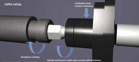
Courtesy of Slater Tools
In a lathe (above), the rotary broach toolholder body is stationary, while its internal live spindle and broach rotate upon contact with the rotating workpiece. In a mill (below), the toolholder body rotates and the workpiece is stationary, while the spindle and broach become stationary upon contact with the workpiece.
Courtesy of Slater Tools
Review the print ads from this magazine to continue
This quick advertiser review unlocks the rest of the article and keeps the full-screen reader focused on the ads instead of the page chrome.


MFGAxis Discussion