Balancing rotating elements in machines
Balancing rotating elements in machines
The rotating elements in machine tools often generate unacceptable forces due to unbalance, and manufacturers usually take corrective action to reduce the forces.
The rotating elements in machine tools often generate unacceptable forces due to unbalance, and manufacturers usually take corrective action to reduce the forces. While it is unusual for end users to perform field balancing, manufacturers of machine tools, spindles, cutting tools, toolholders and other rotating equipment do it routinely. Balancing a thin, disc-like element such as a grinding wheel is often achieved through a procedure called "single-plane balancing."
Unbalanced forces arise because the center of mass is not the same as the center of rotation. Figure 1 shows a thin disc (blue) mounted on a shaft (green) between two bearings (red). Because disc density is not perfectly uniform and the disc is not perfectly manufactured and perfectly mounted on the shaft, the center of mass is not the same as the center of rotation.
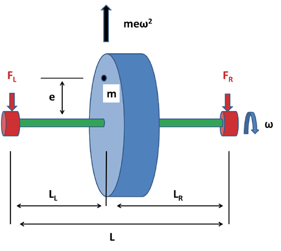
Figure 1. An unbalanced rotating element.
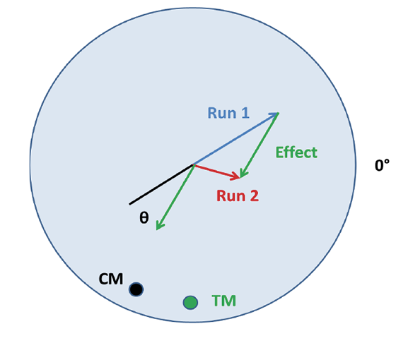
Figure 2. The balancing procedure using a trial mass.
It is convenient to think of the unbalance as a mass (m) off center by a distance (e) on an otherwise perfect wheel. As the shaft rotates at a speed (ω), the unbalanced mass generates a force equal to meω2, and that force rotates with the disc. At the instant shown, the force pulls the wheel up. But after the shaft rotates 180°, the force pulls the wheel down. The resulting time-varying force causes the wheel to vibrate, and the goal of balancing is to eliminate or counteract the unbalance force. The force is proportional to the square of the rotational speed, so the importance of balancing increases dramatically as shaft speed increases.
Correcting the unbalance requires either adding an appropriate mass, such as a screw, to the light side or removing mass, such as by drilling a hole, from the heavy side. Many rotating elements have premanufactured threaded holes that accept balancing screws.
The location of the unbalanced mass can be determined by mounting the shaft in low-friction bearings, rotating the shaft and allowing it to freely come to rest. If there is unbalanced mass, the heavier side will come to rest at the bottom. This location can be marked and the test repeated multiple times. If the disc is balanced, the marks will be randomly distributed, but, if it is unbalanced, the marks will be clustered.
The size of the unbalance can be determined by trial and error or calculated if the reaction forces in the bearings can be measured. The reaction force on the left bearing is FL = (LR/L)meω2, and the reaction force on the right bearing is FR = (LL/L)meω2 (Figure 1). Those two equations are enough to solve for the only unknowns (m and e). Any combination of m and e that produces the same product will work as a correction mass.
A single-plane balancing strategy for systems that do not rotate freely requires a test mass and an encoder. A position on the encoder is chosen as the reference point, marked 0° in Figure 2. The shaft is rotated at the operating speed, and the size of the maximum force and the corresponding encoder reading at the time of the maximum force are recorded.
The magnitude of the force and the angle with respect to 0° are plotted in Figure 2 as the blue vector, or run 1. That is the effect of natural unbalance. Then, a small trial mass (TM), such as a screw, is added, and the procedure is repeated. The size of the maximum force changes and occurs at a different encoder position, shown in Figure 2 as the red vector, or run 2.
The difference between the two run vectors is the effect of the added mass alone. That is, the effect of the natural unbalance plus the effect of the trial mass equals the effect observed in run 2. It is shown as the green, or effect, vector. The trial mass is then removed, and the size of a correction mass (CM) to be added is calculated. CM is equal to the trial mass divided by the length of the effect vector times the length of the run 1 vector.
The angle (θ) between the effect vector and the run 1 vector is the same as the angle between the trial mass and the correction mass. Rather than add a correction mass, the same amount of mass could be removed from a location at the same radius and 180° from the correction mass location. CTE
About the Author: Dr. Scott Smith is a professor and chair of the Department of Mechanical Engineering at the William States Lee College of Engineering, University of North Carolina at Charlotte, specializing in machine tool structural dynamics. Contact him via e-mail at [email protected].